SYMPTOM
CAUSE AND REMEDY
26. Frequency
counter
LED does not
light
when
FM
or
FM MUTE
button
is
pressed
in.
A) Diode D803
defective
Replace the
diode.
B) Capacitor
C701, C704, C810
Replace the defective
capacitor(s).
27.
Frequency
counter misreads in AM
or
FM
reception.
A)
Defective
crystal
XR701
Replace
the crystal.
B) Defective
lC 1C701
or transistor TR702-TR705
Replace the defective
component(s).
28.
Frequency
counter misreads in
only
AM
reception.
A)
Defective AM
switch
53
Replace
the switch.
NOTES
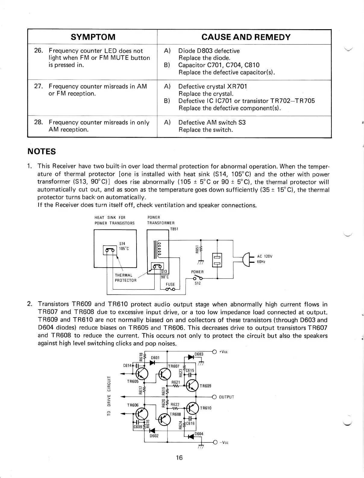
1. This Receiver have two
built-in over load thermal
protection
for
abnormaloperation.
When
the temper-
ature of
thermal
protector
[one
is installed
with heat
sink
(S14,
105'C)
and the other with
power
transformer
(S13,
90'C)] does
rise abnormally
(105
t
5"C
or 90
+
5oC), the thermal
protector
will
automatically cut out, and as
soon as the temperature
goes
down sufficiently
(35
t
t5'C),
the ther.mal
protector
turns back-on
automatical ly.
lf
the
Receiver
does turn itself
off, check
ventilation and speaker
connections.
HEAT
SINK Ft)R
POWER
POWER TRANSISTORS
TRANSFOEIVIEB
2. Transistors
TR609 and TR610
protect
audio output stage when abnormally high
current
flows in
TR607
and TR608 due
to excessive input
drive, or a too low impedance load
connected at output.
TR609
and TR610 are not
normally
biased
on and collectors of
thesetransistors
(through
D603and
D604
diodes) reduce biases
on
TR605
and TR606. This decreases drive to
output
transistorsTR60T
and TR608
to reduce
the
current. This occurs not
only
to
protect
the circuit but also the speakers
against
high level
switching clicks
and
pop
noises.
AC I2OV
60Hz
+Vcc
F
=
a
E
-
E
o
o
F
TH E R I\4AL
PROTECTO R
 Loading...