rc
0
-J
CO
Page 13, 14
TRANSMITTER SECTION ALIGNMENT CHART & RECEIVER SECTION ALIGN ENT CHART
Control Setting: CH 19 should be CH9.
Page 17
NOISE BLANKER ALIGNMENT CHART
Control Setting: CH19 should be CH9 27.115 MHz,
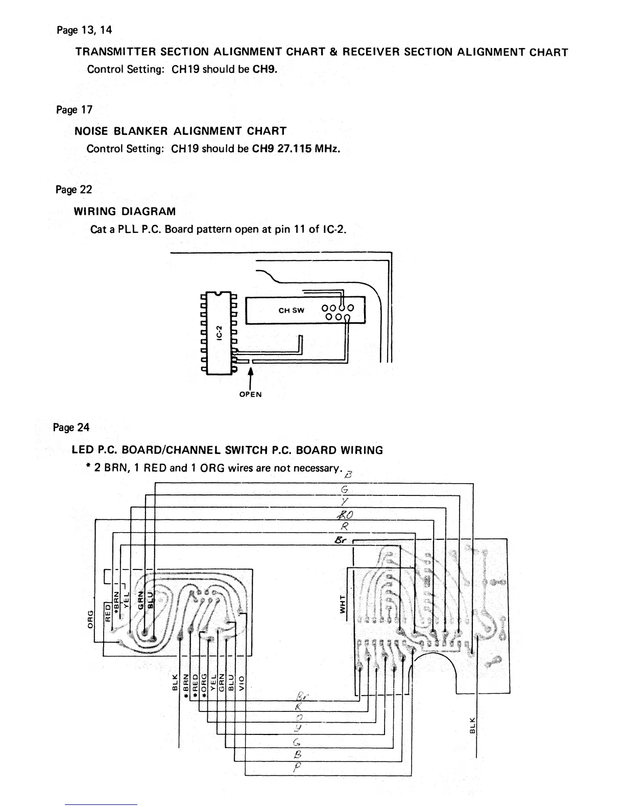
Page 22
WIRING DIAGRAM
Cat a PLL P.C. Board pattern open at pin 11 of C-2.
OPEN
Page 24
LED P.C. BOARD/CHANNEL SWITCH P.C. BOARD WIRING
* 2 BBN, 1 RED and 1 ORG wires are not necessary.
L.,