RTL8773B Motherboard User Guide
14
·Copyright 2019 Realtek Semiconductor Corporation.
All Rights Reserved.
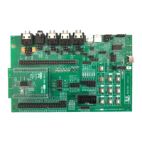
2.2.3 Keys and LEDS
Before using Keys and LEDs on evaluation board, their control pins should be
connected to RTL8773B Motherboard IOs. Default pin assignment is provided by
directly shorting jumper on J3、J6、J44 and J45 as shown in Figure 2-4.
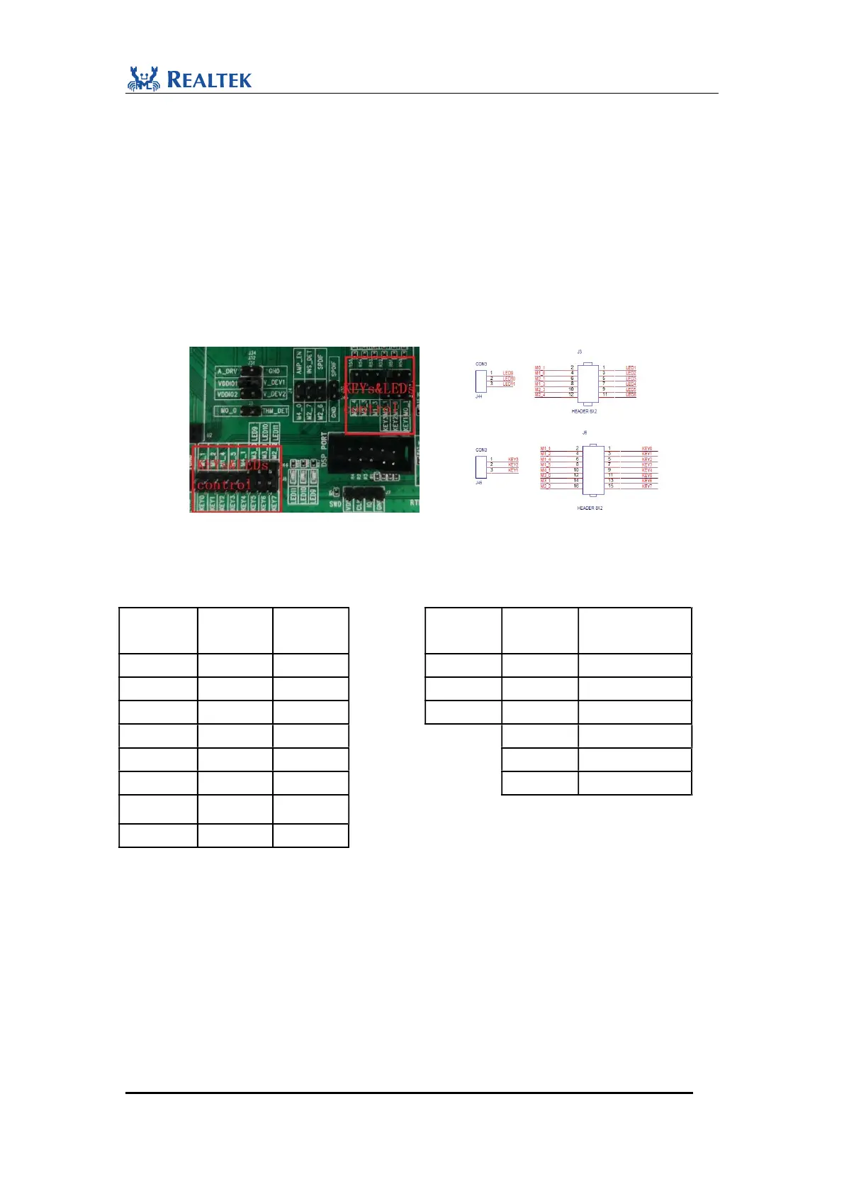
The default mapping table for LEDs and KEYs is shown as Table2-1. Control pins of
Keys and LEDs on J3、J6、J44 and J45 can be connected to different RTL8773B
Motherboard IOs. For example, Key0’s control pin on J6 is Pin2. By putting jumper
wire on J6.1 and J6.2, we can read key value through M1_1.
Figure 2-4 Keys and LEDs Control jumper
Table 2-1 Keys and LEDs Map
LEDS name
Pin
name
Keys
name
Keys
name
Pin
name
LEDS name
M1_1
KEY0
KEY1
M0_1
LED1
M1_2
KEY1
KEY2
M1_0
LED2
M1_4
KEY2
KEY3
M2_1
LED3
M1_5
KEY3
M1_3
LED4
M4_1
KEY4
M2_3
LED5
LED9
M3_0
KEY5
M2_4
LED6
LED10
M3_1
KEY6
LED11
M2_2
KEY7
Tips: One KEY and LED cannot be connected to two IOs at the same time.
In addition, as shown in Figure2-5, the Keys with pull-up resistors (KEY0, 2, 4, 6
marked by red arrows) are all active-low, while the Keys with pull-low resistors
(KEY1, 3, 5, 7 marked by blue arrows) are all active-high. Users can choose
either of two types according to the specific development requirements.