REC Installation Manual - REC Alpha Series - IEC /
Rev A . Ref: NE
PANEL INSTALLATION
REC solar panels are designed for capturing solar radiation and are not suitable for use as overhead or vertical glazing. The IP rating of the junction
box provides a level of protection that allows panels to be mounted in any orientation. There are different options for securing REC solar panels
depending on the design of the array. Mounting hardware is not supplied by REC. Ensure the mounting structure can withstand anticipated wind and
snow loads. Follow the mounting hardware manufacturer’s instructions and recommendations at all times.
Installing the REC Alpha Series solar panels with clamps and rails has been found to comply with IEC & IEC requirements for
downward pressure,e.g., snow, of up to Pa ( Pa design load
*
) and upward pressure,e.g., wind, of up to Pa ( Pa design load
*
)
according to the following instructions (
*
design loads apply a safety factor of . to the stated test load, e.g., test load Pa / . = Pa
design load). Site-specific factors such as high wind or snow levels must be taken into consideration to ensure this limit is not exceeded.
RAIL SPECIFICATIONS
When installing on mounting rails, ensure they run underneath the panel and provide support to the frame. The positioning of the rail must ensure
that the minimum clamp grip length and the central point of the fixation, e.g., the bolt, is fully within the required clamping zone as indicated on the
following pages.
CLAMP SPECIFICATIONS
Clamp installation must be carried out according to the manufacturer’s instructions, including specific hardware and torque requirements.
Ensure the clamps used are suitable for the planned installation and expected system design loads.
• The grip area must not extend onto the panel glass and/or cause cell shading,
• Avoid the application of excessive pressure to prevent frame deformation.
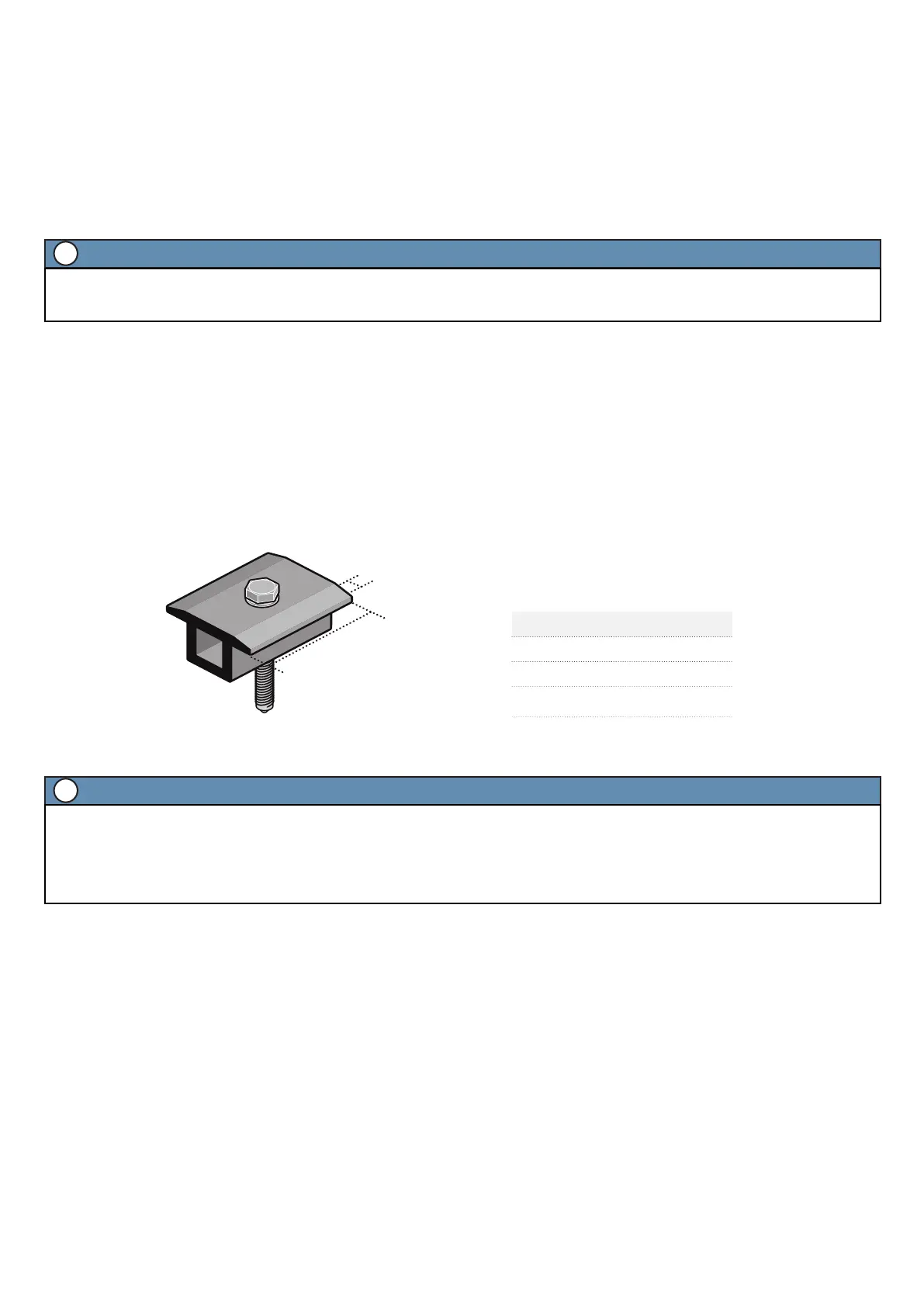
Fig. : Clamp specifications: Mid-clamps
Min. grip length: mm
Grip depth: - mm
NOTE
• In areas of snow build-up, panels can be subjected to forces in excess of the stated limit even when snow depth does not appear extreme,
causing damage to the framework. If the installation may be affected by this, further panel support is recommended, especially on the lower
row of panels.
• In the case of any questions regarding mounting systems, or if the mounting system to be used does not match any of the instructions shown
in this installation manual, please contact REC for further support.
i
Specifications Length
Grip length mm - mm
Grip depth mm
Torque
See manufacturer’s
instructions
NOTE
Panels must be installed so that the cells are not shaded as this will drastically reduce electrical output. If partial shading is inevitable at certain
times of the day or year, it must be kept to an absolute minimum. Remove any labels or stickers that may be on the front of the panels and ensure
no residue is le on the glass.
i
 Loading...