REC Installation Manual - REC Alpha Series - IEC /
Rev A . Ref: NE
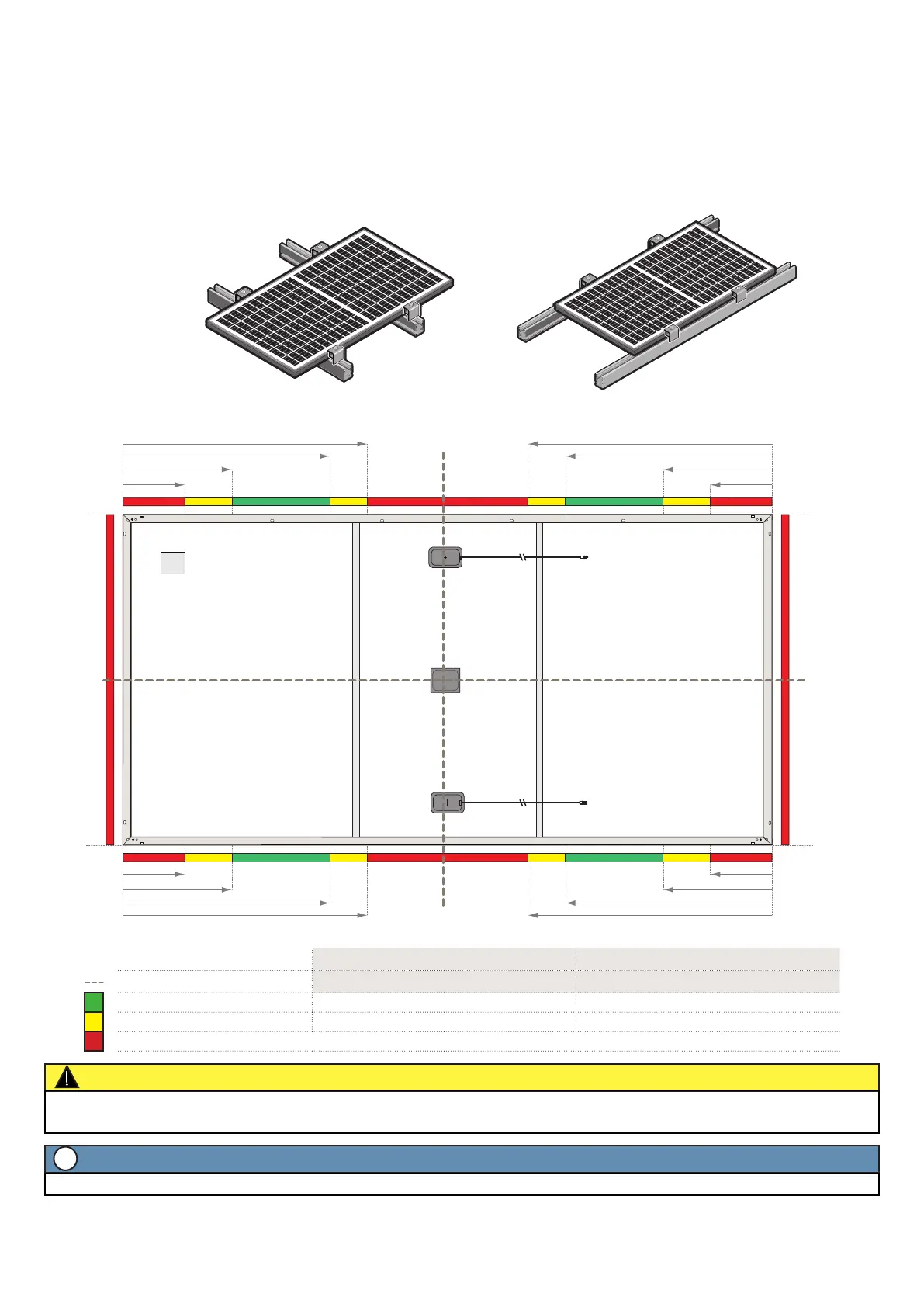
MOUNTING METHODS: CLAMPING WITH RAILS PARALLEL TO THE SHORT SIDE
The rails must run underneath the panel to provide support to the frame. Where the rails are positioned parallel to the short side of the panel as in
fig. , the clamping zones shown in fig. are to be followed:
• Each panel must be clamped in a minimum of four separate zones, with one clamping point in each quarter of the panel (fig. ).
• The distance between the end clamp and the end of the rail must be a minimum of mm.
• Follow the clamp manufacturer’s instructions to install the clamps, including the recommended applied torque.
• The position of the rails must ensure that the minimum grip length of the clamp and the central point of the fixation, e.g., the bolt, is fully within
the required clamping zone.
Fig. : Clamping of panels with rails parallel to short side
Fig. : Clamping zones for panels with rails parallel to short side
CAUTION
The minimum grip length of each clamp and its center point must be fully located in the same color zone to be rated to that load value (fig. ). If
the panel is secured in two different zones, it is rated to the lower load value only.
NOTE
If required, any further clamps, i.e., ≥, may be clamped elsewhere on the panel, including in the red zone without affecting the warranty.
i
a) Long side mounting b) Short side mounting
0
350 mm [13.8 in] 350 mm [13.8 in]
350 mm [13.8 in] 350 mm [13.8 in]
200 mm [7.9 in]
200 mm [7.9 in]
200 mm [7.9 in]
200 mm [7.9 in]
780 mm [30.7 in] 780 mm [30.7 in]
780 mm [30.7 in] 780 mm [30.7 in]
655 mm [25.8 in] 655 mm [25.8 in]
655 mm [25.8 in]
655 mm [25.8 in]
0
0
0
GR
GR
GR
GR
0 0
00
Legend: Test Load Design Load
(= Test load / 1.5)
Panel quarter division
Max. downward load Max. upward load Max. downward load Max. upward load
- mm Pa Pa Pa Pa
- mm; - mm Pa Pa Pa Pa
Not permied (in cases where only four () clamping points are used, additional clamps, i.e., ≥ may be freely located on panel frame)
 Loading...