-3-
Released 2017-10-31 Drawing No. LP0951D
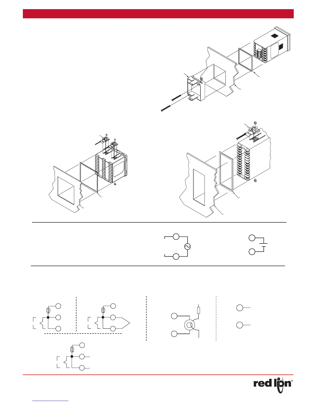
INSTALLING THE CONTROLLER
The controller is designed to be mounted into an enclosed panel. The
unit must be inserted in the case during installation of the controller.
Instructions:
1. Prepare the panel cutout to the proper dimensions.
2. Assemble the mounting clip by inserting the nut into the slot and then
insert the screw and thread through the nut as shown (See drawing)
3. Slide the panel gasket over the rear of the controller, seating it against
the lip at the front of the case.
4. Insert the controller into the panel cutout. While holding the
controller in place, install the panel latch(es) and then slide it
to the farthest forward slot possible.
5. To achieve a proper seal, tighten the panel latch screws evenly until
the controller is snug in the panel, torquing the screws to 13.9 to 20.8
oz-in (9.8 to 14.7 N-cm). Overtightening can result in distortion of the
controller, and reduce the effectiveness of the seal.
Note: The installation location of the controller is important. Be sure to
keep it away from heat sources (ovens, furnaces, etc.) and away from
direct contact with caustic vapors, oils, steam, or any other process
by-products in which exposure may affect proper operation.
7
8
9
10
11
12
PANEL LATCH
(SUPPLIED W/UNIT)
EXISTING PANEL CUT-OUT
1/16 DIN
1.77” (45.0 mm) X 1.77” (45.0 mm)
PANEL GASKET
1/16 DIN Installation
CONTROLLER POWER CONNECTIONS
For best results, the power should be relatively “clean” and
within the specified limits. Drawing power from heavily loaded
circuits or from circuits that also power loads that cycle on and
off should be avoided. It is recommended that power supplied
to the controller be protected by a fuse or circuit breaker.
2
1
N
C 100-240V
50/60 Hz
5VA
INPUT CONNECTIONS
For two wire RTDs, install a copper sense lead of the same gauge and
length as the RTD leads. Attach one end of the wire at the probe and the
other end to input common terminal. This is the preferred method as it
provides complete lead wire compensation. If a sense wire is not used,
then use a jumper. A temperature offset error will exist. The error may be
compensated by programming a temperature offset.
12
11
10
IN
T
C
+
-
+
-
TC-
TC+
IN
T
C
+
-
+
-
12
11
10
DC+ VOLTAGE/CURREN
DC- VOLTAGE/CURRENT
IN
T
C
+
-
+
-
12
11
10
VAC
RTD and Resistance
Thermocouple and Millivolt
Voltage and Current
1/8 DIN Installation
20
24
23
22
21
14
17
19
18
15
16
13
(2) PANEL LATCH
(SUPPLIED W/UNIT)
PANEL
GASKET
EXISTING PANEL CUT-OUT
1.76" (44.5 mm) X 3.60" (91.5 mm)
(4) PANEL LATCH
(SUPPLIED W/UNIT)
PANEL
GASKET
EXISTING PANEL CUT-OUT
3.58" (91.0 mm) X 3.58" (91.0 mm)
1/4 DIN Installation
0 V
24V AC/DC
2
1
+
VAC/VDC
USER 1/CT1/REMOTE
LOAD
+
-
-
+
CT Input
USER 1/CT1/REMOTE
+
-
-
+
DC- VOLTAGE/CURRENT
DC+ VOLTAGE/CURRENT
Remote Input

 Loading...

