INSTALLATION
Typical Installation
3
INSTALLATION
Typical Installation
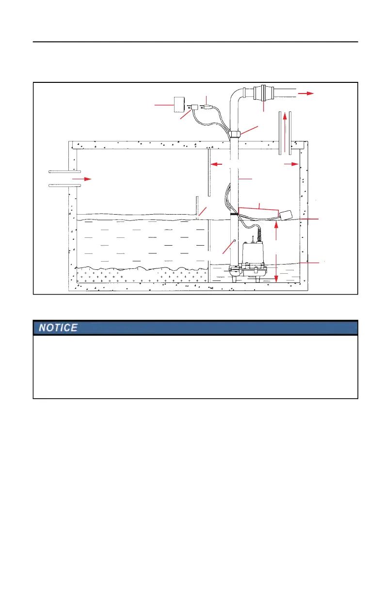
Physical Installation
1. Install the pump in the center of a suitable gas-tight basin that is at least 18-inches diameter and
24-inches deep.
• Provide adequate room for future servicing, protection from freezing temperatures, flooding,
and equipment drainage.
• Never place the pump directly on clay, earth, or gravel surfaces.
• Ensure sump is clean and free of nails, gravel, string, cloth, or other debris before installing.
IMPORTANT: Do not attempt to restrict the intake side of the pump.
2. Connect discharge piping, using pipe joint compound at all connections.
• The discharge pipe should be as short as possible and contain as few elbows as possible.
• Ensure piping is the same diameter as the discharge port.
• If reduced flow rates are required, place a valve on the discharge side of the pump.
3. Install a union in the discharge line just above the basin cover.
4. Install a free flow check valve in the discharge line that will easily pass
11
/
16
-inch solids.
Scum
Septic Tank Chamber
In Flow
Bae
Tank Vent
Tank/basin
minimum size 1.5 ft (.5 m)
Union
DischargePump Power Cord
Check Valve
Float switch piggyback plug
(automatic models only)
Discharge Pipe
Outlet minimum
4 ft (1.2 m) above floor level
STOP
Minimum 4" (10.2 cm)
free length of cable
2 ft
(.6 m)
Air Relief Bleed Hole
Sediments
START
Risk of damage to pump or other equipment.
• Support pump and piping when assembling and when installed. Failure to do so may cause piping to break, pump
to fail, motor bearing failures, etc.
• Do not install the check valve in a vertical position, as solids may settle in the valve and prevent the valve from
opening on start-up. For best performance of the check valve when handling solids, install it in a horizontal posi-
tion or at an angle of no more than 45°.
 Loading...