WARNING - RISK OF ELECTRICAL SHOCK
• Have an electrician provide electrical power to the motor.
• Motor must be grounded and terminal cover in place to
reduce electrical shock hazard.
• Keep motor operating area as dry as possible.
• A ground fault interrupter (GFI) protected circuit is
recommended for use with any electrical device operating
near water.
• Always disconnect power before servicing.
• Not investigated for use in swimming pool areas.
WARNING - ELECTRICAL PRECAUTIONS
All wiring, electrical connections, and system grounding must
comply with the National Electrical Code (NEC) and with any local
codes and ordinances. Employ a licensed electrician. For non-
thermally protected motors use with approved motor control that
matches motor input in full load amperes with overload element(s)
selected or adjusted in accordance with control instructions.
SAFETY
CAUTION
• DO NOT OPERATE THIS PUMP DRY!
• Review instructions before operating.
CAREFULLY READ THESE SAFETY
MESSAGES IN THIS MANUAL AND ON PUMP.
FOR DUAL VOLTAGE MOTORS:
Voltage change instructions are located on motor label or on wiring
access cover.
PERFORMANCE
This pump is suitable for installations where the vertical distance
from the pump to the water level does not exceed 25 ft. In all
installations, friction losses in the suction pipe must be taken into
consideration.
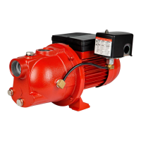
APPLICATION
RLSP
LAWN AND TURF PUMPS
ELECTRIC MOTOR DRIVEN
Model HP
Discharge Pressure in PSI
Max.
PSI
10 20 30 40
Capacities in U.S. GPM
RLSP-75 3/4
58 39 29 7
43
RLSP-100 1 63 46 38 7 45
RLSP-150 1-1/2 71 53 44 15 44
RLSP-200 2 89 69 60 36 47
RLSP-250 2-1/2 97 90 74 47 48
VOLTAGE WIRING INSTRUCTIONS - UP TO 1-1/2 HP
Voltage change device
Terminal board
Figure 1
Figure 2
Figure 3
SAFETY WARNINGS
BEFORE OPERATING OR
INSTALLING THIS PUMP, READ
THIS MANUAL AND FOLLOW ALL
SAFETY RULES AND
OPERATING INSTRUCTIONS.
NOTE: DO NOT move the white lead wires on L1 & L2.
Figure 1 shows the motor switch before the voltage change device
is pressed onto the voltage terminals.
Figure 2 shows the motor switch set for 115V. The voltage change
device is pressed onto both terminals, with the arrow on the
voltage change device pointing to the 115V arrow on the terminal
board.
Figure 3 shows the motor switch set for 230V. The voltage change
device is pressed onto only one terminal, with the arrow on the volt-
age change device pointing to the 230V arrow on the terminal board.
1
P. O. Box 12010
Oklahoma City, OK 73157-2010
Ph/Tél/Tel: 888.956.0000
Fax/Téléc: 405.228.1561
www.RedLionProducts.com