Auxiliary Power Outputs
The camera provides two auxiliary power output connectors on its back panel. Each supplies un-
regulated +11.5 to 17V battery pass-through power. Maximum sustained current draw is 1.5
Amp per output. The outputs are over-current protected, and are activated by the camera on
boot up. If the over-current circuits trip, power cycle the camera to re-activate the outputs.
Mating connector LEMO FGG.0B.304.CLAD42Z
Functions of the GPI and GPO pins can be configured by the operator, however the default
setting for the upper connector is Pin 2 = Record Start/Stop and Pin 3 = Record Tally. For the
lower connector, the default setting is Pin 2 = Record Next Frame and Pin 3 = Record Com-
pleted. This preset is suitable for animation or motion control applications.
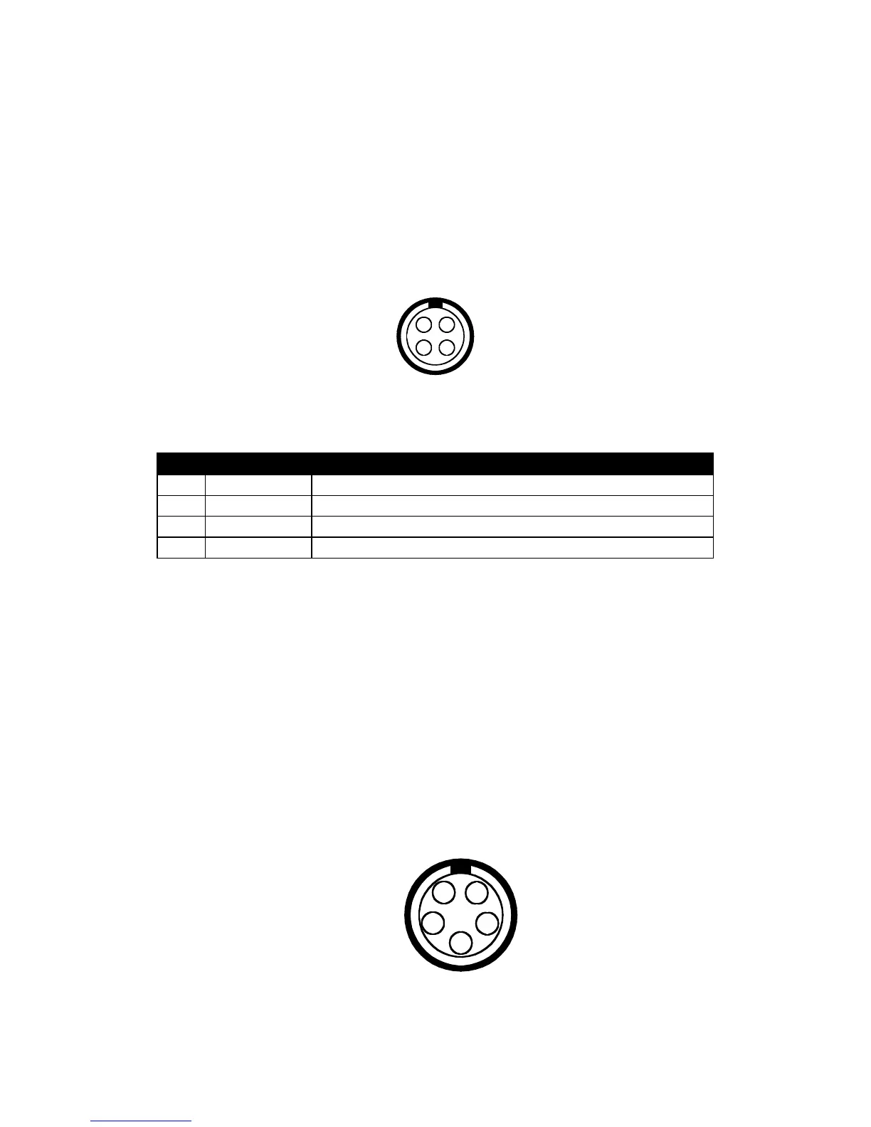
Timecode Input / Output
This connector supports SMPTE Timecode input and output. Pins 2 and 3 may be used together
to receive a balance SMPTE 12M serial time code input, or pin 2 may be used by itself (leave pin
3 open) to receive a single-ended SMPTE 12M serial time code input. Pin 5 is time code output.
Mating connector: LEMO FGG.0B.305.CLAD42Z