Note: Pins 4, 6, 9 and 10 are reserved for future use.
RED-EVF Interface
The RED-EVF interface is a custom digital video and power interconnection between the camera
and a RED-EVF. Due to the data integrity nature of this interface, the pin-out is not published.
Contact RED technical support for details of available RED-EVF cable lengths.
RED-LCD Interface
The RED-LCD interface is a custom digital video and power interconnection between the camera
and a RED-LCD. Due to the data integrity nature of this interface, the pin-out is not published.
Contact RED technical support for details of available RED-EVF cable lengths.
Note: The Aux 232, RED-EVF and RED-LCD connectors use the same shell size. Do not at-
tempt to force fit a 10-pin Aux 232 cable into a 16-pin RED-EVF or RED-LCD connector, or
force fit a 16-pin RED-EVF or RED-LCD cable into a 10-pin Aux/RS232 connector.
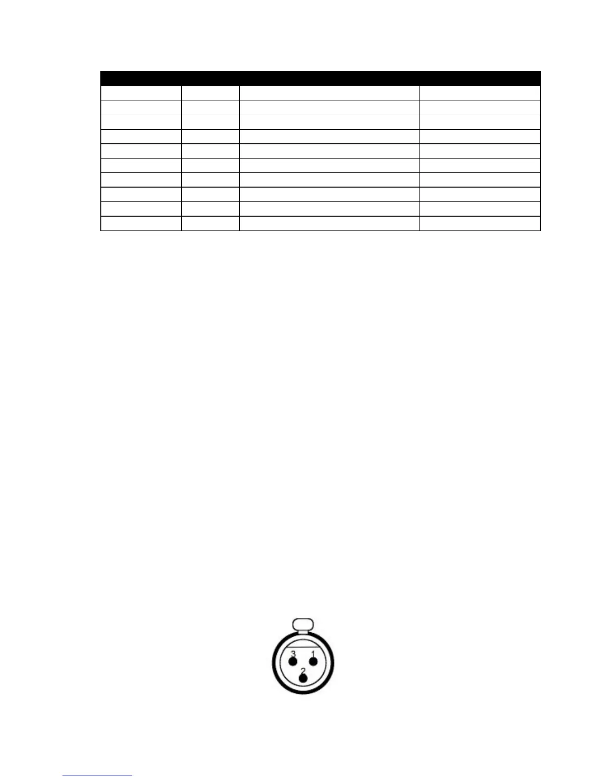
Line/Microphone Audio Inputs
A three-pin mini-XLR connector is provided for each of four discreet line / microphone inputs.