www.altronics.com.au
Redback® Proudly Made In Australia 3
Redback® A 4488 Paging Console
6.0 Connecting the Paging Console/s and the A 4489A Audio Switcher
The Paging console/s and Audio Switcher are connected by CAT5e cables with a maximum run distance of 300 metres.
This CAT5e cable can be connected to either of the two RJ45 ports provided on the rear of the microphone. A 24V DC
power supply rated at a minimum of 1A is required to power the system. Power connection must be made by connecting
power to the Audio Switcher via a 2.1mm DC Jack. Power is then fed through the CAT5e cables to supply power to the
paging consoles. We recommend tting the power supply with the Altronics P 0602 2.1mm DC Plug with collar which can
be screwed onto the DC socket to prevent accidental disconnection of power.
The balanced audio output from the microphone is transmitted down the CAT5e cable to the Audio Switcher which splits
and converts the signal to microphone and line level outputs. These are provided as screw terminal connections.
Volume controls for the microphone volume and chime volume are located on the rear of the microphone.
Connection Congurations
There are three basic different congurations for switching the audio output from the A 4489A Audio Switcher to the
output zones.
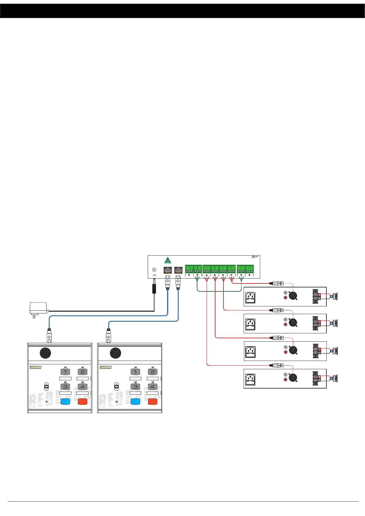
Option 1 : Individual Zone Ampliers using Microphone Level Signals
The audio from the paging console/s is fed down the Cat5e cable to the A 4489A audio switcher. Take the low level
balanced signal from the “Mic Out” terminals on the rear of the A 4489A and feed them back into the “Audio In”
terminals on the rear of the A 4489A as shown in Fig 3.
The audio from the “Zone 1” to “Zone 4” terminals are then fed into individual amplifers to provide the audio for the
four zones. The audio from these output terminals are switched internally by relays and are not present unless the zone is
activated by the paging console/s.
Use this method if using ampliers with low level balanced inputs. If the ampliers used have line level inputs use the
conguration outlined in option 2.
Fig 3
Option 2 : Individual Zone Ampliers using Line Level Signals
The audio from the paging console/s is fed down the Cat5e cable to the A 4489A audio switcher. Take the line level
(1V balanced signal) from the “Line Out” terminals on the rear of the A 4489A and feed them back into the “Audio In”
terminals on the rear of the A 4489A as shown in Fig 4.
The audio from the “Zone 1” to “Zone 4” terminals are then fed into individual amplifers to provide the audio for the
four zones. The audio from these output terminals are switched internally by relays and are not present unless the zone is
CAT5 cable
Max 300M
MIC LEVEL SIGNAL
Typical connection of the A 4488/s and A 4489A with individual ampliers for each zone using mic levels
4 Zone Communicator
System Busy
Page
BGM
All Call Cancel
A 4488
4 Zone Communicator
System Busy
Page
BGM
All Call Cancel
A 4488
240V AC @ 50Hz
Fuse 800mA
Line Mic
L
R
OUTPUT
+
–
2 1
3
240V AC @ 50Hz
Fuse 800mA
Line Mic
L
R
OUTPUT
+
–
2 1
3
240V AC @ 50Hz
Fuse 800mA
Line Mic
L
R
OUTPUT
+
–
2 1
3
240V AC @ 50Hz
Fuse 800mA
Line Mic
L
R
OUTPUT
+
–
2 1
3
ZONE 1 AMPLIFIER
ZONE 2 AMPLIFIER
ZONE 3 AMPLIFIER
ZONE 4 AMPLIFIER
24V DC POWER SUPPLY
SUCH AS M 8968C PLUGPACK
OR SIMILAR 24V 1 AMP SUPPLY.
POWER MUST BE CONNECTED
AT THE A 4489 LINE OUT BOX.
www.altronics.com.au
Made in Australia
by Altronic
Distributors Pty Ltd
To Paging Consoles
24V
DC IN
+
+
-
Audio In
+-
+-+-
+-
+-
+-
Zone1Zone2Zone3Zone 4Mic OutLine Out
+
-
BGM In
 Loading...