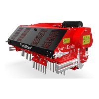
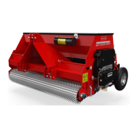
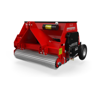
The Verti-Drain® is a robust and specialized machine designed for the treatment of lawns and other grassed areas, primarily for aeration and soil conditioning. Its core function is to create holes in the ground, which helps to alleviate soil compaction, improve water penetration, and promote healthier root growth for turf. The machine is not an independently operating unit and requires an appropriate tractor for its operation, forming a tractor/Verti-Drain® combination.
Function Description
The Verti-Drain® operates by using a series of pins to penetrate the ground. These pins are attached to a crankshaft assembly, which drives their vertical movement into and out of the soil. The machine's design allows for precise control over the working depth and the angle of the pins, enabling various types of aeration depending on the specific needs of the turf. The pins can be either solid, designed to break open compacted soil, or hollow, which remove cores of soil to facilitate top dressing and further reduce compaction.
The machine's operation involves a PTO (Power Take-Off) shaft that transmits driving force from the tractor to the Verti-Drain®. This PTO shaft is a critical component, and its correct installation, length, and maintenance are essential for safe and effective operation. A slip coupling is integrated into the PTO shaft to protect the machine from short-duration overloading, though it does not protect against long-duration overloading.
Usage Features
Before operation, several checks are crucial. The area to be treated must be inspected for loose obstacles and irregularities. The Verti-Drain® should be connected to the tractor according to instructions, ensuring a clear view for the operator. Safety stickers, located on the sideboard and back cover, must be clearly visible and legible, as they provide important warnings regarding moving parts and safe distances.
The operating depth of the pins can be adjusted by loosening nuts on both sides of the machine and turning a spindle. Each rotation of the spindle changes the depth by 4 mm (0.160"). An indicator on the side of the machine shows the depth setting, which is calibrated for 200 mm (8") long pins. If shorter pins are used, the difference in length must be subtracted from the indicated value.
The pin angle can also be adjusted simultaneously using two spindles located at the front of the machine. A 90-degree angle is recommended for hollow pins and 8 mm (5/16") pins, as it minimizes draught and creates a "clean" hole. Angles between 90 and 65 degrees increase draught and are advised for solid pins, depending on ground conditions and desired effect. Proper installation of the machine, ensuring a 90-degree angle relative to the ground, is vital to prevent damage.
Driving speed directly influences the hole separation in the driving direction. The Verti-Drain® does not require a creep gear, but a slow driving speed is necessary for a small hole distance. The input speed of the PTO shaft should not exceed 500 rpm. If hard objects are anticipated in the soil, the speed must be reduced, and the transmission set to position 1. Heavier pins, specific applications, or maximum pin angles may cause pin holders to float, necessitating a reduction in speed to prevent them from being forced upward.
The start procedure is critical to prevent damage. The machine should be driven to the starting point, lowered until the lowest knives are almost touching the ground, and the tractor motor set to approximately 1200 rpm. After shifting the tractor to the correct gear and driving forward, the PTO shaft is engaged, and the machine is carefully allowed to sink into the ground while moving. Only then should the PTO shaft speed be increased to the maximum allowable. Stopping involves decreasing motor speed, raising the machine out of the ground, disengaging the PTO shaft, and raising the pins at least 120 mm above the ground. It is strictly forbidden to place the machine in the ground without a rotating PTO shaft or to drive in reverse with the pins in or near the ground. A hydraulic top rod should not be used.
The machine is designed for use on slopes with a maximum gradient of 20 degrees, always working downhill. Before use, the ground should be checked for cables or pipes, and the operating depth adjusted accordingly (60% of their depth). If the soil is frozen or very wet, operation should be postponed. For very compact soil, shorter pins or an adjusted operating depth are recommended.
For transport on public roads, national traffic regulations must be observed. On open fields, a maximum speed of 12 km/h (8 mph) should not be exceeded due to the machine's weight. When the machine is in the raised position, at least 20% of the tractor's weight should be supported by the front axle.
Disconnecting the Verti-Drain® involves opening the rear cover, turning the crankshaft to position central pin holders in their top positions, folding up other pin holders, setting the machine on solid ground with both rollers, locking the rear guide, blocking rollers, removing the top rod, PTO shaft, and lower tractor arms. The tractor motor should be off if people are around, and for long-term storage, it's recommended not to fold up the pins to preserve shock-absorber springs.
The Verti-Drain® 7120 can be equipped with a turf hold-down kit to prevent the turf layer from coming loose. These kits are available for both 12 mm (1/2") and 18 mm (3/4") pins and are mounted to a pre-installed main beam. Plates are fastened to the main beam and aligned with the pins through slotted holes. If plates bend over time, their direction can be reversed. If pins contact the sides of slots, pin blocks should be realigned. If pins contact the front of the hole during use, the drawbar length should be checked.
Maintenance Features
Regular maintenance is crucial for the Verti-Drain®'s longevity and safe operation. Before each use, the machine should be inspected for loose bolts, nuts, and parts. Hydraulic hoses should be checked for damage or wear and replaced if necessary with manufacturer-specified hoses. Pressure must always be relieved from the hydraulic installation before any work is performed. Protective covers and safety decals must be present and intact.
Monthly maintenance of the slip coupling is required. This involves removing the upper PTO cover, loosening all bolts/nuts by two turns, running the machine at a very low speed in the field, and stopping after 10 seconds if the coupling slips. If it doesn't slip, bolts should be loosened further or annual maintenance performed. Once the coupling has slipped, bolts/nuts should be retightened until it functions properly again, but not immediately to the previous setting.
Annual maintenance of the slip coupling includes removing the PTO from the machine, checking all parts for damage, and replacing any worn components. The slip coupling should be disassembled, all parts cleaned, and then reassembled, tightening bolts and nuts until springs are adjusted to 33 mm (1.3"). Both sleeves should be greased, and the PTO halves reassembled and mounted.
After the first 20 operating hours (for new or repaired machines), the PTO, roller bearings, and crankshaft bearings should be lubricated with EP 2 lubricating grease. Bolts and nuts should be checked and tightened to the correct torque. The machine should be connected to the tractor and run without load for five minutes, listening for strange noises and movements. Oil levels in the gearboxes should be checked (they should be at the center of the gauge glass) and SAE 140 oil used if necessary. The transmission should be checked for oil leaks, and seals/sealing paste replaced if needed.
Every 50 operating hours, the PTO, roller bearings, and crankshaft bearings require lubrication. Bolts and nuts should be checked and tightened. The machine should be run without load for five minutes to check for unusual noises or movements. Gearbox oil levels should be checked, and the transmission inspected for leaks.
Every 500 operating hours, the oil in the gearbox should be replaced with SAE 140.
The crankshaft assembly requires specific attention. If parts are replaced, the crankshaft may be difficult to turn due to pre-tension. This can be alleviated by tapping against the center of each crank, starting near the gearbox, alternating left and right, until the throw settles into place and the crankshaft turns more easily. After crankshaft repairs, nuts must be regularly checked for looseness. Cranks must be mounted on the correct side of the machine.
If an element is out of alignment, it can be corrected by loosening the four bolts/nuts connecting the crankshaft to the element and the two bolts connecting the element to the frame. The element can then be moved sideways until it aligns with adjacent elements, and all bolts and nuts are retightened. Overloading can cause misalignment, and realignment is necessary whenever a throw is replaced to prevent extra tension and damage to bearings and other parts.
Used oil and grease are harmful to the environment and must be disposed of according to local regulations. Only original Verti-Drain® parts should be used for maintenance and repairs to ensure continued safety. Only authorized technical personnel should carry out adjustments and repair work. A record of repairs should be kept.