23
- If the area isn’t clean, check the gap between the rubber seal strip N and the blade spring tension
T. Extra weight on top of the core collector may help as well.
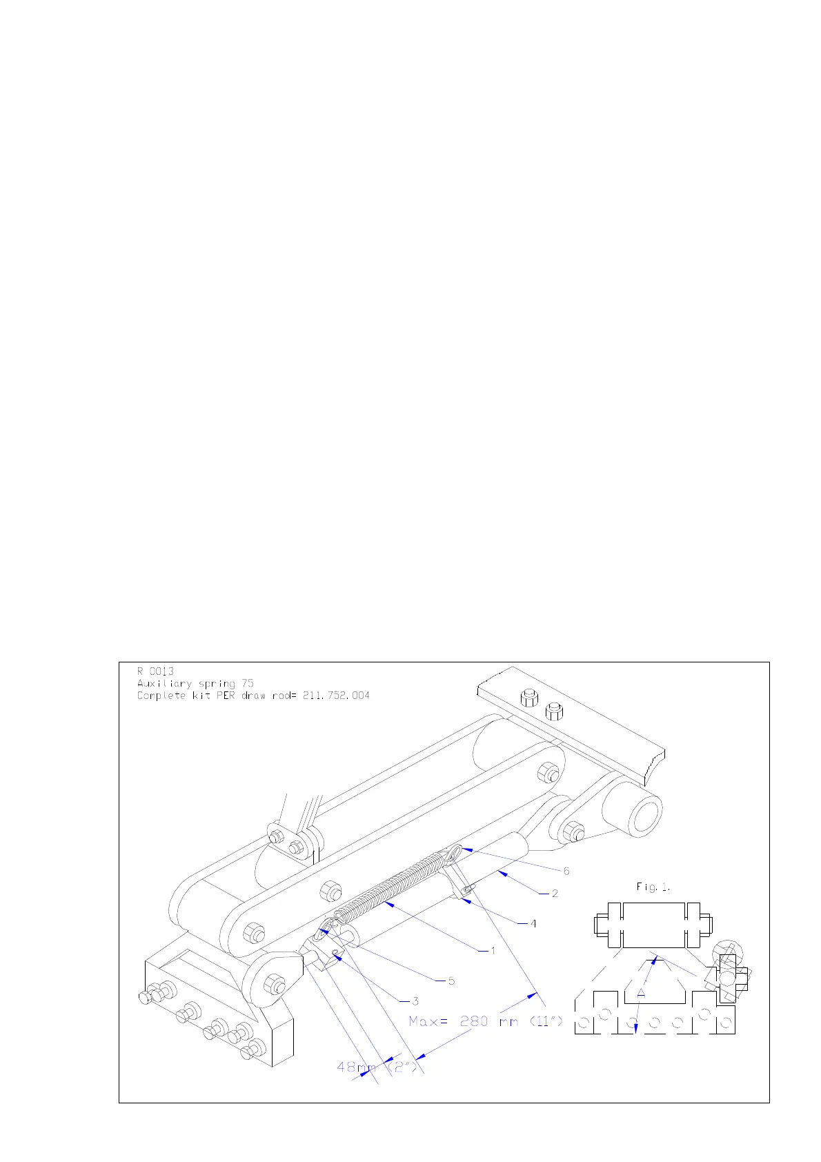
16.1.4 AUXILIARY SPRING KIT
In some cases, people want more pre tension on the draw rod springs.
A complete spring kit per draw rod has the part number 211.752.004.. For a 7516 (H) you need 6
kits, for the 7521 (H) 8 and for the 7526 (H) 10 kits.
Mounting instructions
The spring 1 should be exactly above the draw rod assembly 2, see Fig.1. This can be achieved by
the angle A of both clamps 3 and 4.
Start with assembling clamp 3 at a distance of 48 mm ( 2”) from the draw rod head end. This is
critical, otherwise the tineholder can’t be turned up anymore.
Next the other clamp 4 can be positioned at a maximum length of 280 mm ( 11”) away from clamp
3. If the length is more ( measured when the draw rod is in its neutral position), damage to the
springs and other components may occur.
Be very careful in fitting the springs on the eye nuts (5/6), because the spring has to be
stretched, which can be dangerous.
@ It is important to adjust all springs at the same pre tension at a machine. The tension can be
reduced by reducing the length 280 mm. The spring can be taken out as well.
@ The tine holder can be turned upwards, when the assembly is done correctly. Check whether the
springs or eye nuts hit something after the installation.
@ With the auxiliary springs assembled, the capacity may increase, but we still have to be aware of
overspeeding the machine. Like with all other Verti-Drains with a rear roller, the tines may turn
towards the roller and hit the roller for different reasons.