8
SELF HELP
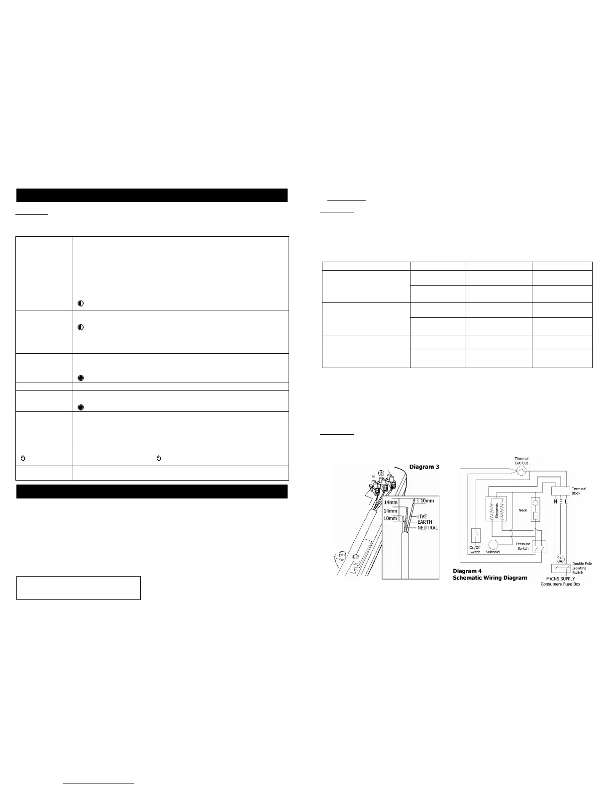
If the shower is not working satisfactorily, make the following checks before calling out the installer
Any one of these adjustments could restore the performance.
The shower cycles
from HOT to COLD
The shower temperature is set too hot causing the thermal cut-out (safety
device) to operate.
Turn inner knob “B” anti-clockwise in the direction of the “blue arrows” to
increase water
Slowly increase the water temperature by turning inner knob “B” clockwise in
the direction of the “red arrows” until a comfortable showering temperature has
been reached.
You MUST WAIT approximately 20 seconds for each adjustment to affect the
water temperature.
“ (medium)” setting may need to be selected.
Water too HOT Increase water flow by adjusting inner knob “B” anti-clockwise (direction of the
“blue arrows”).
“ (medium)” setting may need to be selected.
Increase pressure to water supply e.g. fully open service valve or stop cock.
Check hose is not kinked restricting the water flow.
Clean shower handset.
Water too COLD Check power is on by neon being illuminated.
Decrease water flow by adjusting inner knob “B” clockwise (direction of the “red
arrows”).
“ (high)” setting may need to be selected.
Spray pattern poor Clean the shower handset.
Water takes longer
to heat up
Thermal cut-out has operated after previous use
(automatically resets when unit cools down)
“ (high)” setting may need to be selected.
Water goes cold
while using
shower
Check neon light is on.
Check water pressure has not fallen so far as to let pressure switch cut out,
e.g. Another tap drawing water off.
Raise position of shower handset.
Water continues to
“ (stop)” selected
This is normal.
The shower includes a shutdown feature that means the water will continue to
flow for up to 3 seconds after “ (stop)” has been selected.
Broken parts Please contact our spares department on 0844 372 7750 (UK only).
Fitting instructions are provided with most spares
Please Note:- The fitting of Spare Parts must be supervised by a suitably qualified person.
White 2 metre Shower Hose Cat No. 83792578 Front Cover Cat No. 93597856
Chrome 1.25 metre Shower Hose Cat No. 93797641 Tank-Base Assy (7.2kW) Cat No. 93597858
Chrome Multi-Mode Accessories Cat No. 83595318 Tank-Base Assy (8.5kW) Cat No. 93597859
Chrome Premium Accessories Cat No. 83595319 Solenoid Valve Cat No. 93597868
Chrome Curved Accessories Cat No. 83595320 Neon Cable Assy Cat No. 93593576
Curtain and Rail Pack Cat No. 83792812 Tank Clip Cat No. 93768309
Curtain and Rail Pack with PRV Washer Cat No. 93795817
Non-Slip Mat Cat No. 83792811 Cylinder “O”-Ring Cat No. 93795809
WRAS Water Isolating Valve Cat No. 93792452 Thermal Cut-Out 50/88°C Cat No. 93597871
Handset Cat No. 93597860
Height Adjuster Cat No. 93597861
WHAT TO DO IF THINGS GO WRONG (1)
ADDITIONAL ACCESSORIES COMMON SPARE PARTS
Additional accessories and spare parts can be
supplied against any Credit or Debit cards
from Redring Sales Hotline 0844 372 7750
5
c) ELECTRICAL
WARNING: THIS SHOWER MUST BE EARTHED.
The electrical installation must be in accordance with the current BS.7671 (IEE Wiring Regulations)
and “Part P” of the Building Regulations and/or local regulations
1. The shower unit is designed for a single phase AC electrical supply.
Please check the rating plate on the unit to see what details apply to your shower.
AS A GUIDE ONLY (* Only applies if external earth impedance is less than 0.35 Ohms)
Rating Cable Sizes
Cable Length
4.0mm²
6.0mm²
32A Type B MCB
21m Max.
.
6.0mm²
10.0mm²
40A Type B MCB
27m Max.
45m Max.
6.0mm²
10.0mm²
40A Type B MCB
27m Max.
8.5 / 7.8kW 240 / 230V
6.0mm²
10.0mm²
45A BS.1361 fuse
12m Max.*
21m Max.*
6.0mm²
10.0mm²
40A Type B MCB
27m Max.
9.5 / 8.7kW 240 / 230V
6.0mm²
10.0mm²
45A BS.1361 fuse
12m Max.*
21m Max.*
Remember to upgrade the cable if it runs in thermal insulation in a loft, or for a longer distance.
2. A means for disconnection in all poles must be incorporated in the fixed wiring in accordance
with the wiring rules.
We recommend a ceiling switch mounted in a convenient position.
3. Cut back cable as in Diagram 3. Connect cable to terminal block making sure that all the
retaining screws are VERY TIGHT and that no cable insulation is trapped under the screws.
WARNING: FAILURE TO COMPLY WITH THESE INSTRUCTIONS COULD RESULT IN
FAILURE OF THE TERMINAL BLOCK
4. Re-Fit the corner section back into the backplate.