* For cable runs over 10 metres or where cable is not flat clipped and surface mounted,
the larger size is the minimum required.
A means for disconnection in all poles must be incorporated in the fixed
wiring in accordance with the wiring rules.
If the unit is fitted in a Bathroom:
A standard 45 amp cord operated isolator switch is recommended.
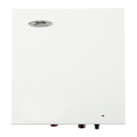
Wiring the Powerstream-Eco
The unit has been designed to accept up to 16mm² supply cable.
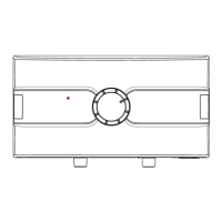
It will be necessary to cut the rubber entry grommet
(diagram 6, point X to X) to enable 10mm² and 16mm²
to be correctly installed.
No cutting is required for 6mm² cable.
In all cases the outer sheath of the cable MUST project
through the grommet (diagram 6), if side entry is used.
This will prevent water getting into the unit.
Strip back the insulation on the LIVE (brown or red)
and NEUTRAL (blue or black) mains wires about 8mm.
Strip back any insulation on the
EARTH (green/yellow or green) about 20mm.
Feed the cable through the side or rear entry grommets, as appropriate.
Connect the cables to the terminal block and earth stud (diagram 6)
Make sure that the live and neutral terminal block screws are tightened securely (1Nm minimum)
Make sure that the earth wire is wrapped around its terminal stud and into the saddle washer.
The nut should be tightened securely (2Nm minimum).
WARNING: FAILURE TO COMPLY WITH THESE
INSTRUCTIONS COULD RESULT IN
FAILURE OF THE TERMINAL BLOCK
Fit the front cover and tighten the retaining nuts.
Fit the retaining nut covers (see diagram 7).
Ensuring the earth continuity
If the unit is fitted in a bathroom, to conform with the current BS.7671 (formally IEE regulations),
the units earth continuity conductor must be effectively connected to ALL exposed metal parts of
ALL other appliances in the room.
 Loading...