33
Assembly drawings 7 and 8:
GentlytightentheM3x10screwsandcheckthatthecardanshaftsarerunningsmoothly.
Assembly drawing 9:
Usethenedetachableseamoftheaxeltoensurethatthesteeringknucklesarepositionedcorrectlywheninserting
thequick-releaseaxles.TheslotsintheM3x15clampingscrewsmustformalinewiththeseam.Beforeinsertingthe
quick-releaseaxles,makesurethecomponentsarecorrectlyaligned.
Assembly drawing 10:
Applysomethread-lockinguidtothecardanshaftbolt(A)beforescrewingitin.
Assembly drawings 11, 12 and 13:
Therearaxleanglegearshouldbeassembledinthesamewayasthefrontaxle.Themaingearcannowbeinserted
intheaxlehousing.
Assembly drawing 14:
Again,usethecentrelineoftherearaxeltopositionyourselfwheninsertingthequick-releaseaxles.Theslotsinthe
M3x15clampingscrewsmustformalinewiththeseam.Again,makesurethatthecomponentsareproperlyaligned
with one another.
Assembly drawing 15:
Applysomethread-lockinguidtothecardanshaftbolt(A)beforescrewingitin.
Assembly drawing 16:
Before installing the steering servo, select the right steering lever for the servo. One of the three supplied levers can
be mounted depending on the servo shaft gearing. Alternatively, you can use a lever of suitable length that comes
with the servo.
Important!
The servo lever must be mounted facing forward in the direction of travel when the steering control on
the transmitter is in the middle position (see also Figure 2 below in this manual). To do this, power up the
remote control unit and check the position of the servo lever.
Do not overtighten the screws on the servo, otherwise the two plastic mounts will warp. The loops on the mounts are
usedlatertoafxtheservocable.
Assembly drawing 17:
Thediagramsshowtheinstallationofthefrontaxle.
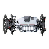
Assembly drawing 18:
Thediagramsshowtheinstallationoftherearaxle.