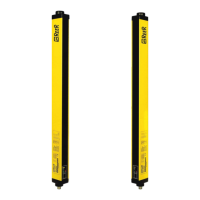
The neighbouring sets should be operated in the reverse direction with
synchronisation beams in opposition as shown below (figure 11).
REFLECTING SURFACES
REFLECTING SURFACESREFLECTING SURFACES
REFLECTING SURFACES
The effective opening angle of the beams and the alignment tolerance for
the emitter and the receiver are approximately ±4° in compliance with the
prEN 61496-2 European project norm.
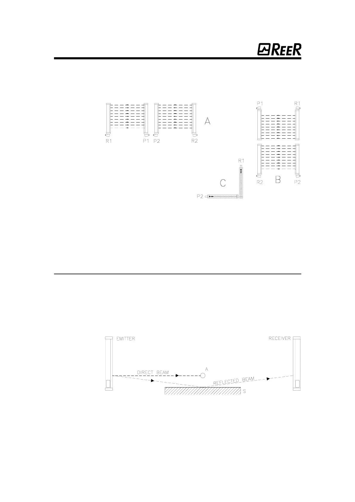
Since reflecting surfaces within the detection zone can cause light deflection
(see fig. 12) and therefore non-detection of an obstacle, a minimum
distance d should be observed.
Fig. 11
Fig. 11Fig. 11
Fig. 11
Correct assembly of two neighbouring sets.
Correct assembly of two neighbouring sets.Correct assembly of two neighbouring sets.
Correct assembly of two neighbouring sets.
Side-by-side assembly: A
Side-by-side assembly: ASide-by-side assembly: A
Side-by-side assembly: A
Adjacent position of the emitters.
Vertical assembly: B
Vertical assembly: BVertical assembly: B
Vertical assembly: B
Right-angle assembly: C
Right-angle assembly: CRight-angle assembly: C
Right-angle assembly: C
Crossed position of the emitter
and the reciver.
P1, P2: emitters. R1, R2: receivers.
Fig. 12
Fig. 12Fig. 12
Fig. 12
Reflecting surface S can cause light deflection.
Reflecting surface S can cause light deflection.Reflecting surface S can cause light deflection.
Reflecting surface S can cause light deflection.
22
2222
22
 Loading...