MOUNTING AND OPTICAL ALIGNMENT
MOUNTING AND OPTICAL ALIGNMENTMOUNTING AND OPTICAL ALIGNMENT
MOUNTING AND OPTICAL ALIGNMENT
The emitter and the receiver must be installed opposite each other. The
distance between the emitter and the receiver must not exceed the specified
nominal scanning range. Brackets are delivered with AS emitter and
receiver units. The emitter and the receiver should be parallel in the same
plane, at the same height and with connectors on the same side.
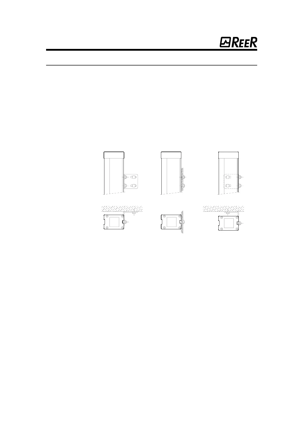
Emitter and receiver modules are equipped with M6 screws (see Dimen-
sions) fixed at the back of the housing. These M6 screws can be used either
for direct mounting with the provided nuts, or in conjunction with brackets
(see figure 15 and figure 16).
The optimum optical alignment between emitter and receiver is essential
for the correct operation of the system. The emitter and the receiver are
equipped with LED’s which help adjust the optical alignment.
To achieve an optimum alignment, the optical axis of the outer beams of
both emitter and receiver must mix up.
Install the receiver and adjust the emitter as follows:
• Adjustment of the synchronisation beam: sight the emitter in
direction of the receiver. Then move the emitter from top to bottom
and from left to right in order to find extreme positions of the
synchronisation beam for which the green LED of the emitter
switches off. This green LED provides information on the synchro-
nisation beam reception. The optimum position is the intermediary
position between extreme positions.
• Adjustment of protective beams: use the synchronisation beam as
a pivot and move laterally the opposite outer beam in order to
find the extreme positions, for which the yellow LED of the receiver
switches off. The optimum position is the intermediary position
between extreme positions.
Fig. 15
Fig. 15Fig. 15
Fig. 15
Mounting of the emitter and receiver units.
Mounting of the emitter and receiver units.Mounting of the emitter and receiver units.
Mounting of the emitter and receiver units.
28
2828
28
 Loading...