Connection diagram A: Direct use of control unit relay outputs.
Connection diagram A: Direct use of control unit relay outputs.Connection diagram A: Direct use of control unit relay outputs.
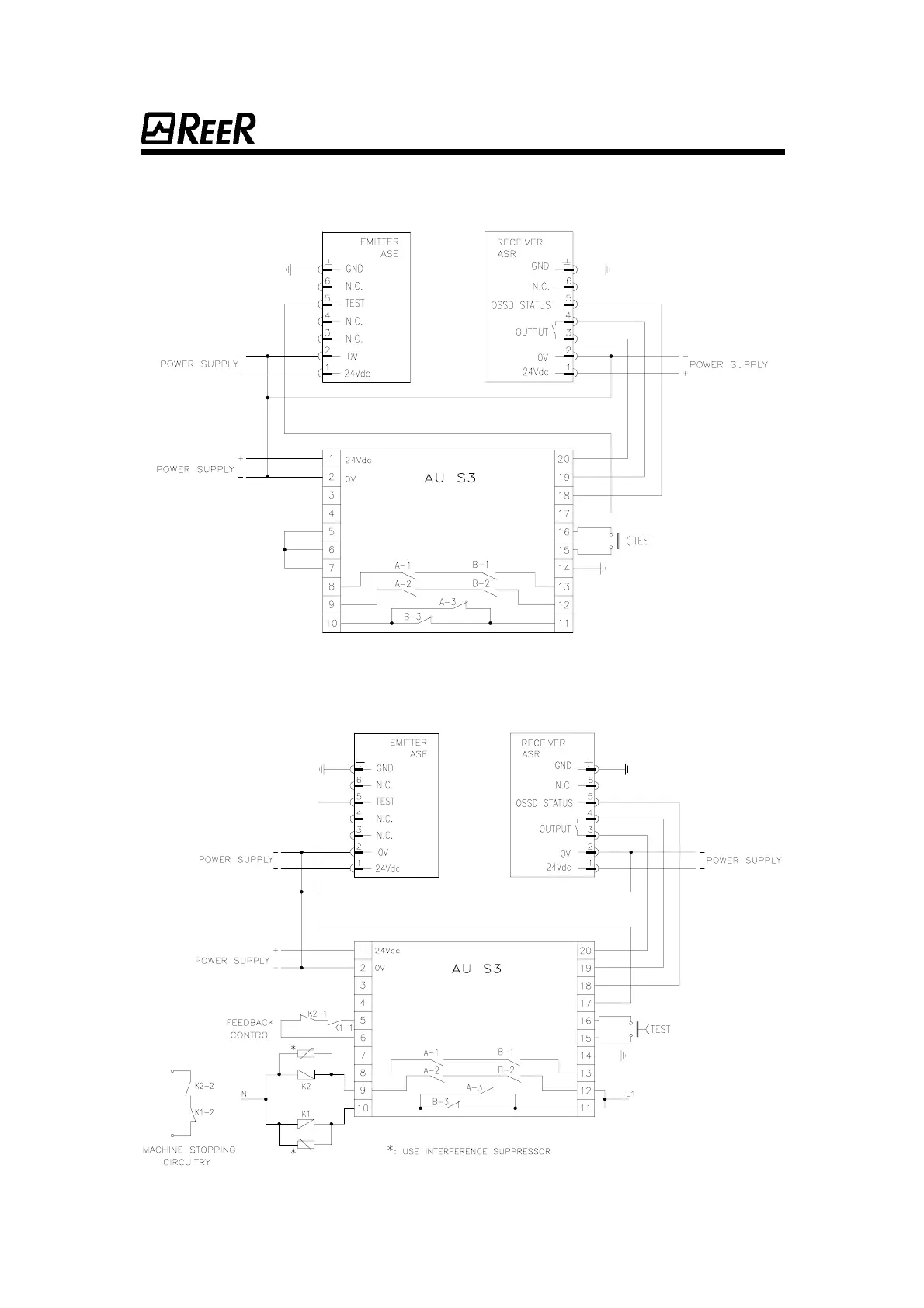
Connection diagram A: Direct use of control unit relay outputs.
Connection diagram B: Use of additional relays K1 and K2.
Connection diagram B: Use of additional relays K1 and K2.Connection diagram B: Use of additional relays K1 and K2.
Connection diagram B: Use of additional relays K1 and K2.
27
2727
27
 Loading...