EasyManua.ls Logo

Reer ARGOLUX AS Series - User Manual

Reer ARGOLUX AS Series
35 pages
Print Icon
To Next Page IconTo Next Page
Loading...
TABLE OF CONTENTS
TABLE OF CONTENTSTABLE OF CONTENTS
TABLE OF CONTENTS
GENERAL OBSERVATIONS
pag.
2
22
2
APPLICATIONS
pag. 2
22
2
DESIGN AND OPERATION
pag. 3
33
3
TEST SEQUENCE AND CONTROLS
pag. 7
77
7
CONTACTS STATUS
pag. 8
88
8
LED STATUS INDICATORS
pag. 9
99
9
TECHNICAL FEATURES
pag
.
10
1010
10
DIMENSIONS
pag.
12
1212
12
INSTALLATION
pag.
15
1515
15
POSITIONING AND SAFETY DISTANCES
pag. 17
1717
17
GROUPING OF SEVERAL SETS
pag. 21
2121
21
REFLECTING SURFACES
pag. 22
2222
22
DEFLECTION MIRRORS
pag. 24
2424
24
ELECTRICAL CONNECTION
pag. 25
2525
25
MOUNTING AND OPTICAL ALIGNMENT
pag. 28
2828
28
INSPECTION AND MAINTENANCE
pag. 29
2929
29
TROUBLE SHOOTING
pag. 30
3030
30
ORDERING CODE, ACCESSORIES AND SPARE PARTS
pag.
32
3232
32
WARRANTY
pag.
34
3434
34
PHOTOELECTRIC
SAFETY
BARRIERS
ARGOLUX
AS SERIES
INSTALLATION AND
MAINTENANCE
MANUAL
Question and Answer IconNeed help?

Do you have a question about the Reer ARGOLUX AS Series and is the answer not in the manual?

Reer ARGOLUX AS Series Specifications

General IconGeneral
BrandReer
ModelARGOLUX AS Series
CategorySafety Equipment
LanguageEnglish

Summary

General Observations

Applications

Describes the industrial machines where the ARGOLUX AS curtain can be used.

Design and Operation

Sensing Function

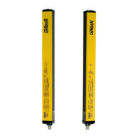
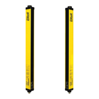
Explains how the emitter and receiver create an invisible protection field using infrared beams.

Test Sequence and Controls

Optical Scanning Circuitry

Details the self-checking principle of the scanning circuitry for correct operation.

Output Circuitry

Describes the control unit's role in managing output relays and system integrity.

Test Input

Covers the periodic performance test required for safety function verification.

Contacts Status

LED Status Indicators

Technical Features

Emitter and Receiver with a Ø35 mm Resolution

Presents technical specifications for models with 35mm resolution.

Emitter and Receiver with a Ø55 mm Resolution

Provides technical specifications for models with 55mm resolution.

Multibeam Models Optic Characteristics

MULTIBEAM Models: Beams Configuration

Illustrates the beam configuration for MULTIBEAM models.

Control Unit AU S3

Details the specifications and features of the AU S3 control unit.

Dimensions (in mm)

Emitters ASE and Receivers ASR

Shows dimensional drawings and specifications for emitter and receiver units.

Deflection Mirrors

Brackets for Mirrors

Details the mounting brackets designed for use with deflection mirrors.

Installation

Positioning and Safety Distances

Vertical Mounting

Provides formulas for calculating safety distance for vertical mounting.

Horizontal Mounting

Provides formulas for calculating safety distance for horizontal mounting.

Versions with a 55 mm Resolution

Discusses suitability of 55mm resolution for specific applications.

Grouping of Several Sets

MULTIBEAM Models Safety and Grouping

Safety distance and grouping rules for MULTIBEAM models, including mounting.

Reflecting Surfaces

Deflection Mirrors

Electrical Connection

Load Features

Specifies load characteristics for output relays and additional relays.

Use of Additional Relays K1 and K2

Explains how to use additional relays for increased contacts or capacity.

Instruction Related to the Connection Cable

Provides guidelines for cable length, shielding, and placement.

Test Command

Details the procedure and requirements for activating the test sequence.

Mounting and Optical Alignment

Inspection and Maintenance

Inspection

Outlines the procedure for testing the safety curtain's response upon machine power-up.

Trouble Shooting

Ordering Code, Accessories and Spare Parts

Ordering Code

Lists product codes for emitters, receivers, and control units.

Accessories

Details available accessories such as deflection mirrors and mounting kits.

Spare Parts

Lists common spare parts like brackets and connectors.

Warranty

Related product manuals