17
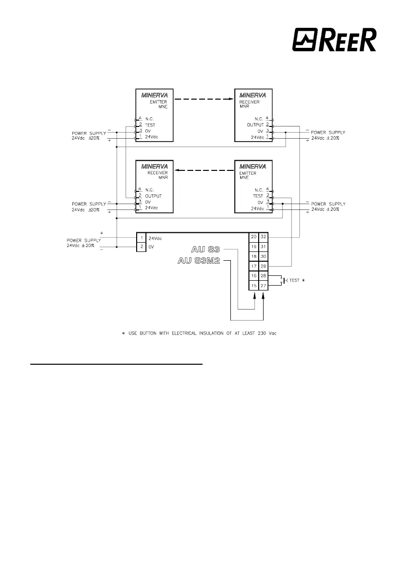
Connection of two pairs of photocells with AU S3 unit or AU S3 M2 muting unit
Mechanical assembly and optical alignment
The emitter and the receiver must be assembled one in front of the other at a distance
not to exceed the effective capacity of the equipment, by means of the fastening brackets
(page 6) supplied as standards: for the assembly of the latter see fig. 9.
As an alternative, the photocell can be fastened by means of the M3 nuts located on its
upper and lower faces.
A perfect alignment between the emitter and the receiver is essential for the flawless
operation of this device. This operation is facilitated by the presence of a green indicator
LED on the receiver. For a correct assembly, perform the following steps:
• Make the electrical connections and fasten the emitter.
• Make sure there are no obstacles in the trajectory of the beam, then move the
receiver in the 4 directions (A, B, C, D) to find the area in which the green LED lights
up. Fasten the receiver in the centre of this area (fig. 9).