12
Electrical connections
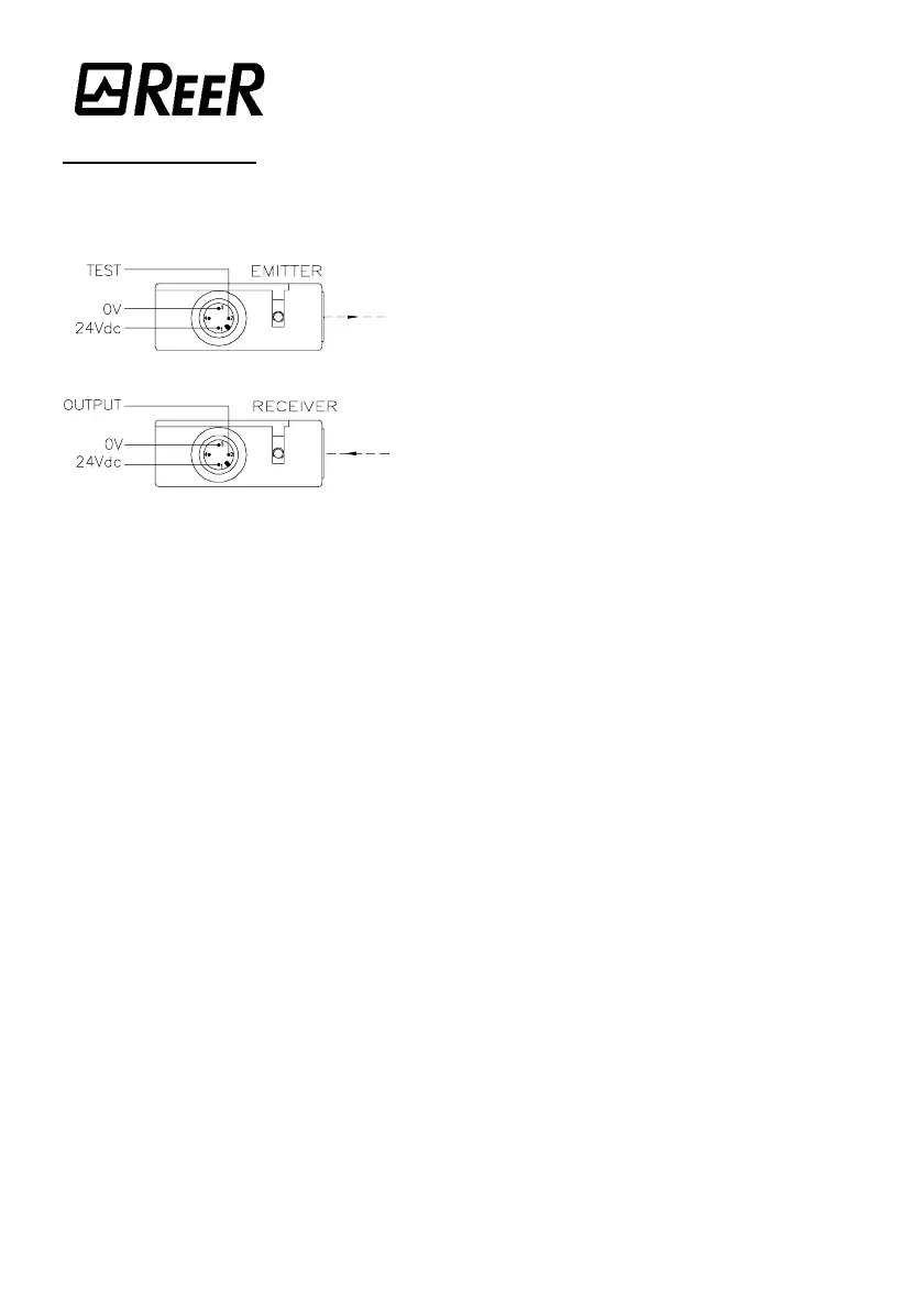
For their electrical connections, MINERVA photocells are equipped with a pole male
connector (fig. 8); it is possible the use of the provided CM9 connector. Make the
electrical connections according to the diagrams shown in pages 13, 14, 15 and 16.
Keep in mind the following considerations:
• Before making the connections, make sure
that the power supply voltage available
conforms to the rating given in the technical
data.
• The photocells and the control units must be
supplied 24V
dc
±20% direct voltage.
• For connections longer than 50m use cables
with cross-sectional area of 1mm
2
.
• We recommend keeping the power supply to the barrier and the control unit
separate from that of other power equipment
(electric motors, inverters, frequency variators)
or other noise sources.
• Connect the control unit to the ground socket.
• The connecting wires between the control unit and the photocell, the connection for
the test control and the connections, if any, for system control (e.g., self-testing)
must follow a different route than the other power cables.
!
To ensure trouble-free operation of the MINERVA photoelectric system it is important to
read some sections of the respective installation manuals, and, in particular:
• "ARGOLUX series AS" Manual:
–
Technical data of the output circuit
–
Use of auxiliary contact elements K1 and K2
–
The TEST control
• "MUTING, AU S3M2 safety unit" Manual:
–
Technical data of output circuit
–
Use of auxiliary contact elements K1 and K2
–
The TEST control
–
Muting sensors
–
–
Technical data of external indicator system
• "AU S-TWIN safety unit" Manual:
–
The TEST control
–
Technical data of output circuit
–
Use of auxiliary contact elements K1 and K2
Fi
ure
Fi
ure Fi
ure
Fi
ure 8
88
8