12
8540571 - 28/04/2008 - Rev.6
MASTER MODELS - 5 poles M12 Secondary connector.
PIN COLOR NAME TYPE DESCRIPTION FUNCTIONING
1
Brown 24VDC -
+24 VDC power supply
-
3
Blue 0VDC -
0 VDC power supply
-
5
Grey PE -
Ground connection
-
2
White SLAVE1 INPUT
4
Black SLAVE2 INPUT
Slave OSSD outputs
readout
According the normative
EN61131-2
(PNP active high)
Table 4
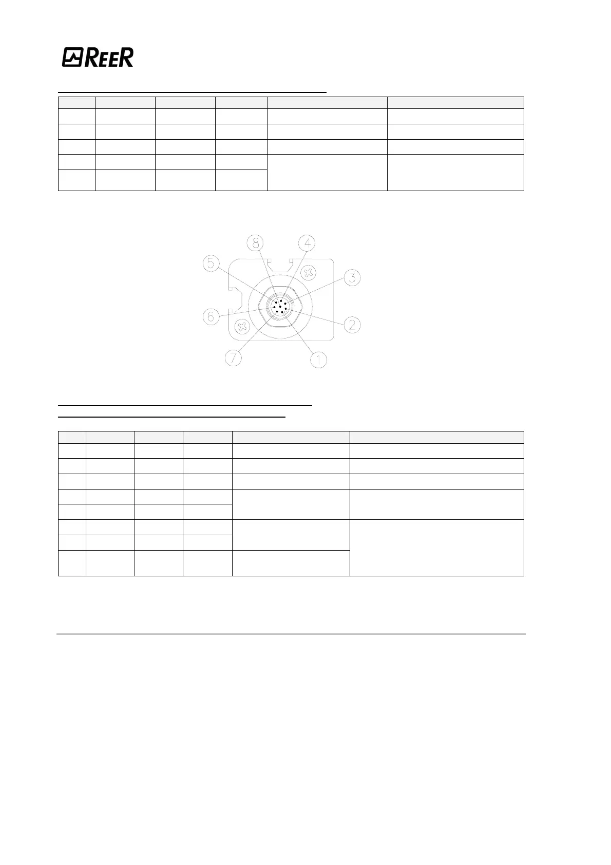
MASTER MODELS - 8 poles M12 Primary connector.
STANDARD MODELS - 8 poles M12 connector.
PIN COLOR NAME TYPE DESCRIPTION FUNCTIONING
2
Brown
24VDC -
+24 VDC power supply
-
7
Blue
0VDC -
0 VDC power supply
-
8
Red
PE -
Ground connection
-
1
White
OSSD1 OUTPUT
3
Green
OSSD2 OUTPUT
Safety static outputs PNP active high
5
Grey
SEL_A INPUT
6
Pink
SEL_B INPUT
Barrier configuration
4
Yellow
K1_K2 INPUT
External contactors
Feedback
According the normative EN61131-2
(ref. Par. "Configuration and operation
modes")
Table 5
WARNINGS REGARDING THE CONNECTION CABLES
• For connections over 50 m long, use cables with a cross-section area
of 1 mm
2
.
• The power supply to the barrier should be kept separate from that to other
electric power equipment (electric motors, inverters, frequency converters) or
other sources of disturbance.
• Connect the Emitter and the Receiver to the ground outlet.
• The connection cables must follow a different route to that of the other power
cables.