32
8540571 - 28/04/2008 - Rev.6
TROUBLESHOOTING
The indications provided on the displays of Emitter and Receiver make it possible to trace
the cause of a system malfunction.
As indicated in the “INDICATIONS” chapter of this manual, in the case of a fault, the system
is blocked and a "F" letter followed by a numeric code identifying the type of fault is shown
on the display of the receiver. (See the tables below).
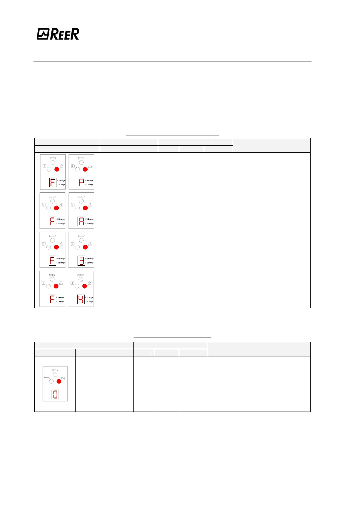
EMITTER (BLINKING SYMBOLS)
7 SEGMENTS DISPLAY LED
SYMBOL MEANING RED GREEN YELLOW
REMEDY
Range selection
incorrect or modified
ON OFF OFF
Carefully check the connection of
terminals 2 and 4
(EXT_RANGE0/1) on the
connector
Internal error
(add-on board)
ON OFF OFF
Internal error
(master board)
ON OFF OFF
Internal error ON OFF OFF
Send the equipment for repair
to the REER laboratories.
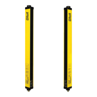
RECEIVER (FIX SYMBOLS)
7 SEGMENTS DISPLAY LED
SYMBOL MEANING RED GREEN YELLOW
REMEDY
Overload of the OSSD
static outputs
ON OFF OFF
Take action in one of the following ways:
• (STANDARD and MASTER MODELS)
Carefully check the connection of terminals
1 and 3 (OSSD) on the connector. If
necessary, adjust load reducing the
current required to max 500 mA (2µF)
• (SLAVE MODELS)
Send the equipment for repair to the REER
laboratories.