8540571 - 28/04/2008 - Rev.6 23
OPERATION AND TECHNICAL DATA
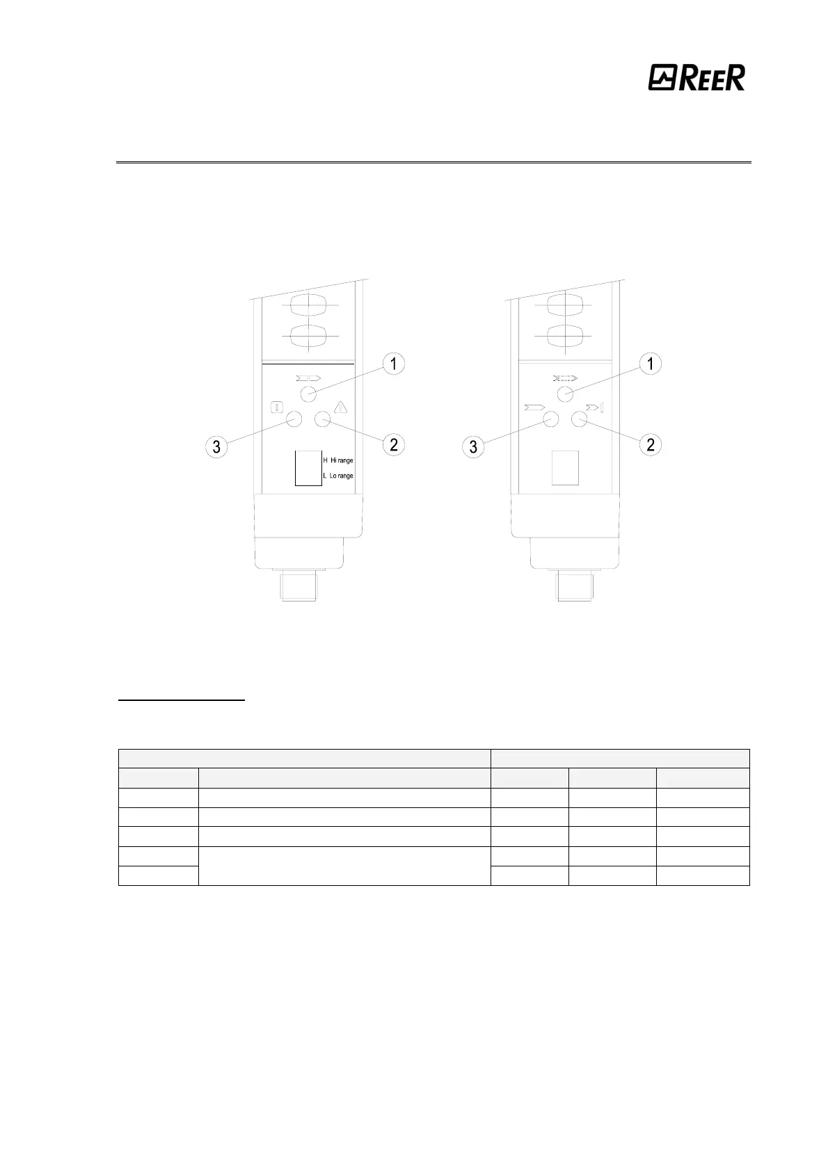
SIGNALS
The symbols showed on the 7 segments display and the leds of emitter and receiver units
are visualized depending on the system operation phase. The tables below shows the
different signals (ref. Figure 22).
EMITTER RECEIVER
Figure 22
EMITTER SIGNALS
Normal operation (FIXED SYMBOLS)
7 SEGMENTS DISPLAY LED
SYMBOL MEANING RED (2) GREEN (3) YELLOW (1)
8
Power on. Initial test ON OFF ON
L
Normal operation. LOW range OFF ON OFF
H
Normal operation. HIGH range OFF ON OFF
L
OFF ON ON
H
TEST
OFF ON ON