Installation
Reflex ex separator — 21.11.2016 English —
Installation and assembly
CAUTION
Escaping hot medium can cause burns.
• Maintain a sufficient distance from the escaping medium.
• Wear suitable personal protective equipment (safety gloves and goggles).
The following items must be considered when assembling and installing the equipment:
• Do not install the device above sensitive components or close to electrical plant.
• Perform installation in dry and frost-proof locations.
• The flow direction is not pre-determined.
• Ensure a vertical and stress-free installation.
– Any stresses that may occur in some cases must be countered by appropriate constructive actions. Stresses may be caused by
temperature effects, for example.
• Ensure the device is readily accessible in its place of installation.
Ensure sufficient bearing capability of the installation site.
– This applies to filling the separator with water in particular.
– If necessary additional structural measures may be required to ensure adequate load
bearing capacity.
The device is not a load-bearing structural element.
– By default, the calculation of the vessels does not take lateral acceleration forces into
account. Avoid alternating stresses such as pressure shocks, abrupt pressure changes, or
strong vibrations.
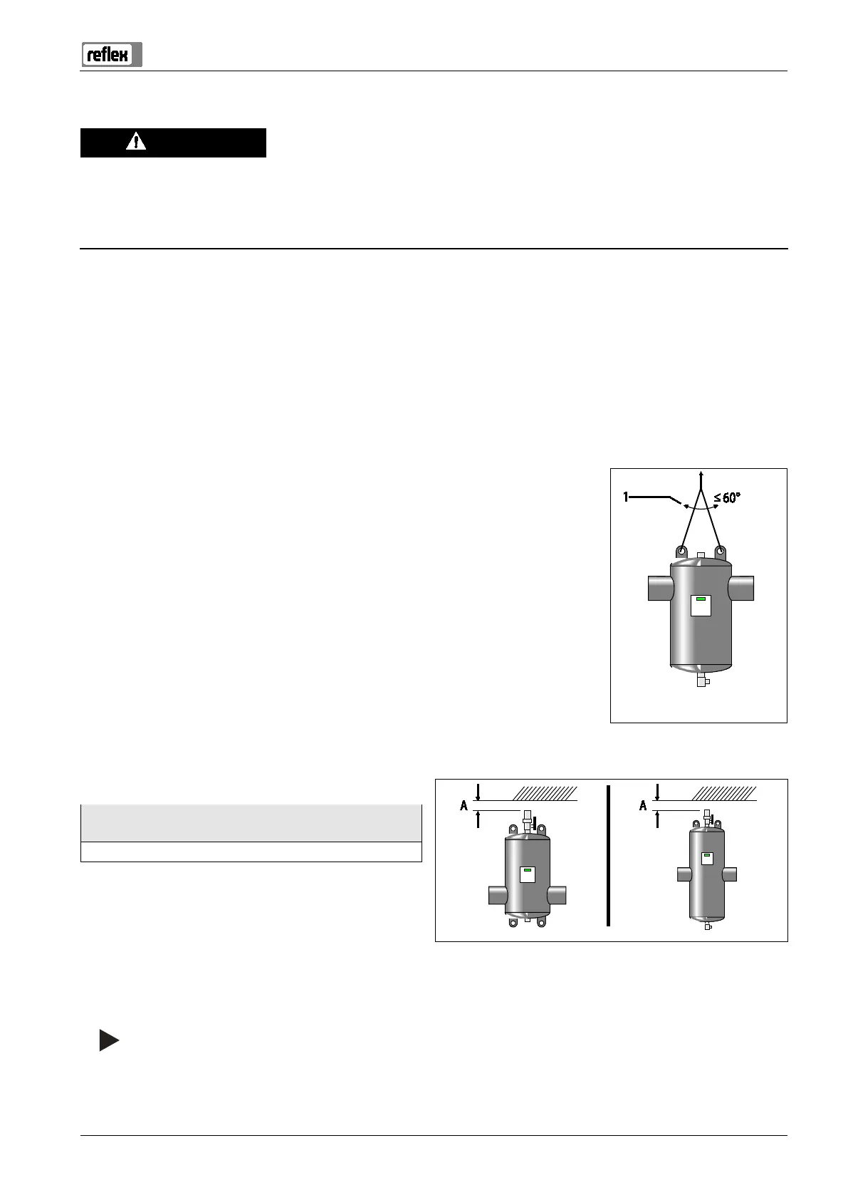
Use only approved transport and lifting equipment.
– The eyes provided on the device are intended solely as installation aids.
The angle (1) of the lifting tackles must be maximum 60°.
After attachment of insulation, attach the additional sticker on the outside so that it is readily
visible.
• Thoroughly rinse the system through after installation of the Reflex Exdirt.
Minimum free space above the top part of the ventilation
Type:
82511xx / 82513xx / 82531xx / 82532xx / 82533xx / 82534xx
50 mm
For connection size DN 450 or greater we recommend
increasing the minimum space requirement to provide access
for servicing of the vent.
Minimum free space below the draw-off tap
• For installation of an Exferro magnetic insert
• For removal of a grid pipe for separators with service flange
You can find a detailed listing of all data at the end of the complete document.
Welded connection only up to DN 300
Cooke Industries - Phone: +64 9 579 2185 Email: sales@cookeindustries.co.nz Web: www.cookeindustries.co.nz