EasyManuals Logo

Reflex Variomat Touch VS 2-1/35 User Manual

Reflex Variomat Touch VS 2-1/35
28 pages
To Next Page IconTo Next Page
To Previous Page IconTo Previous Page
Page #14 background imageLoading...
Page #14 background image
Installation
14 English
Variomat Touch 09.2020 - Rev. A
Terminal
number
Signal
Function
Wiring
X0/3
PE
X0/1
L1
Supply 400 V, maximal 20 A
User
supplied
X0/2
L2
X0/3
L3
X0/4
N
X0/5
PE
Circuit board
1
PE
Voltage supply
Factory-
provided
2
N
3
L
4
Y1
Make-up solenoid valve WV
User,
optional
5
N
6
PE
7
Y2
PV 1 overflow valve (motor ball
valve or solenoid valve)
--
8
N
9
PE
10
Y3
PV 2 overflow valve (motor ball
valve or solenoid valve)
---
11
N
12
PE
13
Dry-run protection message
(floating)
User,
optional
14
15
M1
PU 1 pump
Factory-
provided
16
N
17
PE
18
M2
PU 2 pump
Factory-
provided
19
N
20
PE
21
FB1
Pump 1 voltage monitoring
Factory-
provided
22a
FB2a
Pump 2 voltage monitoring
Factory-
provided
22b
FB2b
External make-up request
together with 22a
Factory-
provided
23
NC
Group message (floating)
User,
optional
24
COM
25
NO
27
M1
Flat plug for supply, pump 1
Factory-
provided
31
M2
Flat plug for supply, pump 2
Factory-
provided
35
+18 V (blue)
Analogue input, LIS level
measuring
at the primary vessel
User
supplied
36
GND
37
AE (brown)
38
PE (shield)
39
+18 V (blue)
Analogue input, "PIS" pressure
measuring
at the primary vessel
User,
optional
40
GND
41
AE (brown)
42
PE (shield)
43
+24 V
Digital inputs
User,
optional
44
E1
E1: Contact water meter
Factory-
provided
45
E2
E2: Insufficient water switch
---
51
GND
Terminal
number
Signal
Function
Wiring
52
+24 V (supply)
PV 2 overflow valve (motor ball
valve), only in VS 2-2
Factory-
provided
53
0 10 V
(correcting
variable)
54
0 10 V
(feedback)
55
GND
PV 1 overflow valve (motor ball
valve)
Factory-
provided
56
+24 V (supply)
57
0 10 V
(correcting
variable)
58
0 10 V
(feedback)
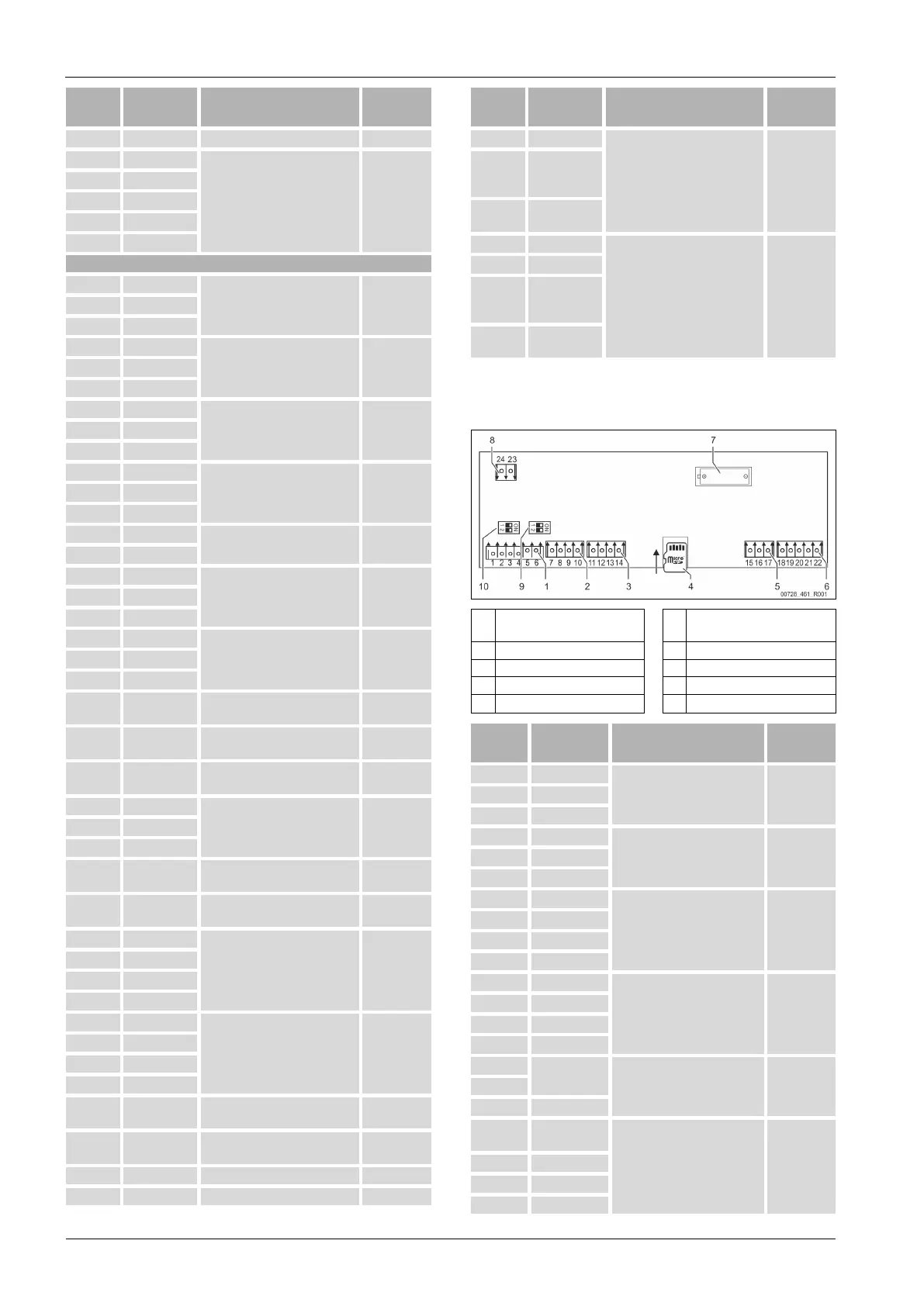
7.5.3 Terminal plan, operating unit
1
RS-485 interfaces
6
Analogue outputs for Pressure
and Level
2
I/O interface
7
Battery compartment
3
I/O interface (reserve)
8
Bus module supply voltage
4
Micro-SD card
9
DIP switch 2
5
10 V supply
10
DIP switch 1
Terminal
number
Signal
Function
Wiring
1
A
RS-485 interface
S1 networking
User
supplied
2
B
3
GND S1
4
A
RS-485 interface
S2 modules: Expansion or
communication module
User
supplied
5
B
6
GND S2
7
+5 V
I/O interface: Interface to the
main board
Factory
8
R × D
9
T × D
10
GND IO1
11
+5 V
I/O interface: Interface to the
main board
(reserve)
---
12
R × D
13
T × D
14
GND IO2
15
10 V~
10 V supply
Factory
16
17
FE
18
Y2PE
(shielding)
Analogue outputs: Pressure
and Level
Standard 4 20 mA
User
supplied
19
Pressure
20
GNDA
21
Level

Table of Contents

Other manuals for Reflex Variomat Touch VS 2-1/35

Questions and Answers:

Question and Answer IconNeed help?

Do you have a question about the Reflex Variomat Touch VS 2-1/35 and is the answer not in the manual?

Reflex Variomat Touch VS 2-1/35 Specifications

General IconGeneral
BrandReflex
ModelVariomat Touch VS 2-1/35
CategoryControl Systems
LanguageEnglish

Related product manuals