6
4.2 PIPING
System piping must be done following industry standards
for good piping practices as well as comply with local codes.
Refer to page 18 for a typical eld piping diagram. After
piping is completed all joints and connections should be leak
tested.
Use top quality copper tubing that is internally free of dirt or
other contaminants.
Equivalent pressure drop from piping should be 15 psi or
lower.
Connect 7/8" OD inlet piping to city water or tank supply.
Connect 5/8" OD outlet piping to unit (7/8" OD for pumping
station with 8 GPM pump).
Connect both 5/8" OD drain outlets.
WATER IN (7/8” OD)
CITY WATER OR TANK
WATER OUT
(5/8” OD - 4 GPM)
(7/8” OD - 8 GPM)
DRAIN (5/8” OD)
DRAIN (5/8” OD)
Figure 2 Piping connections
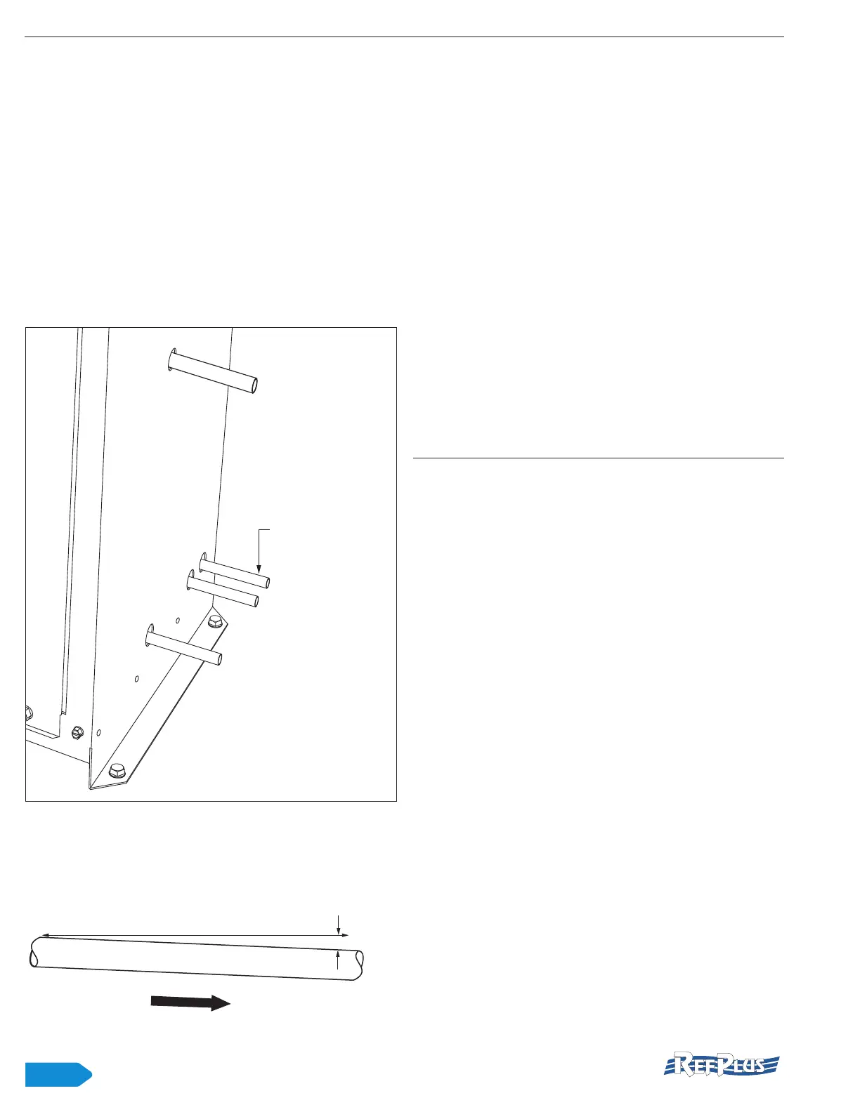
All piping should have a minimum slope of 1/4"/12" away
from the heat rejection unit (fluid/gas cooler or condenser).
12”
1/4”
AWAY FROM COOLING UNIT
Figure 3 Piping slope
4.3 WIRING
IMPORTANT: Wire connections may have come loose
during transit. Check all screws for tightness prior to
starting up the unit.
The pumping station must be grounded.
All system wiring must follow applicable local and
national codes.
Internal wiring of pumping station has been completed at
the factory. Wiring connection ends on terminal blocks in the
control panel and are clearly labeled. Check the nameplate
with the current characteristics to be used for wiring.
Connect the pumping station in accordance with supplied
wiring diagrams.
Systems are available for 120V/1PH/60Hz, 230V/1PH/60Hz
and 208V/3PH/60Hz. Other voltages may be available upon
special request.
IMPORTANT: For a 230V/1PH/60Hz system, 208V/1PH/60Hz
is not acceptable and must be avoided as this could damage
the pump.
5. START-UP
Before starting the adiabatic pre-cooling system for the rst
time, or after system was shut down a long period, always
carry out the following start-up procedure:
• Check water supply
• Check air vent (proper connection)
• Check proper interlock connection
• Check uid and outside temperature sensors (proper
connection)
• Check pulsing valve for proper operation
• Check water particle lter (properly in place)
• Check pump current (consumed)
• Check water pressures (see section 6 below).
• Check unit voltage and compare to wiring diagram
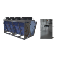
• Check atomizing nozzles for leaks (properly tightened).
Also, make sure nozzles are aiming away from the coil,
at 180
o
, as shown in gure 4. Pipes may have shifted
during transportation.
IMPORTANT: Each adiabatic pre-cooling system comes
with a start-up report form that must be completed during
installation and sent back to RefPlus. This is to insure
proper follow-up from the manufacturer and to activate
the warranty. This form is also available at the end of this
manual or online at refplus.com, under the Service tab.
INSTALLATION START-UP