Regency
®
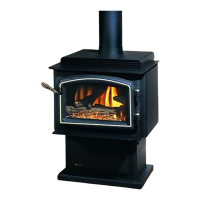
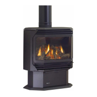
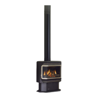
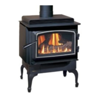
CLASSIC C34-3 Direct Vent Freestanding Gas Stove
11
INSTALLATION
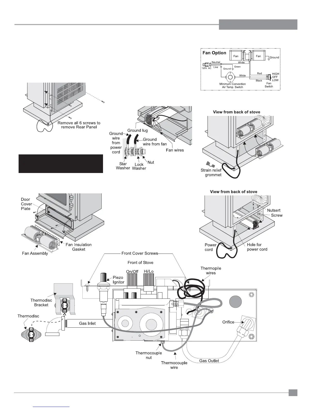
Diagram 3
Caution: Ensure that the wires do not
touch any hot surfaces.
Note: The #8 ground lug is a dedicated
ground for mobile home use only.
9) Lift the fan assembly in through the pedes-
tal and up through the cut out as shown in
diagrams 3 and 4.
2) Remove valve cover plate by removing 2
screws.
3) Remove wire from piezo ignitor.
4) Screw the four 8-32 x 3/4 screws provided
into the nutserts as shown in diagram 3. Do
not tighten screws.
5) Push all the fan wires through the hole on
the fan assembly. See diagram 2.
Diagram 2
OPTIONAL FAN INSTALLATION
Diagram 1
1) Open pedestal door and remove door cover
plate by removing 4 screws. See diagram
1.
IMPORTANT
Disconnect power supply
before servicing
For leg unit: remove 7 screws, remove bottom
access panel and install fan assembly,
follow steps 4 to 17.
For pedestal unit: To install the fan in an
installed stove-access from front
through the pedestal by following the
directions below. If the stove is not
installed - access through rear and
follow steps 4 to 17.
6) Put power cord (shown in diagram 3) through
the hole and pull through to the front of the
unit for easier installation of ground wire.
7) Place the fan assembly partially in door
cover plate hole. See diagram 2.
8) Attach the 2 ground wires (green) to the
ground lug as per diagram 2.
Note: Ground lug is located on the bottom
of the fan assembly. See diagram
2.
Diagram 4