76
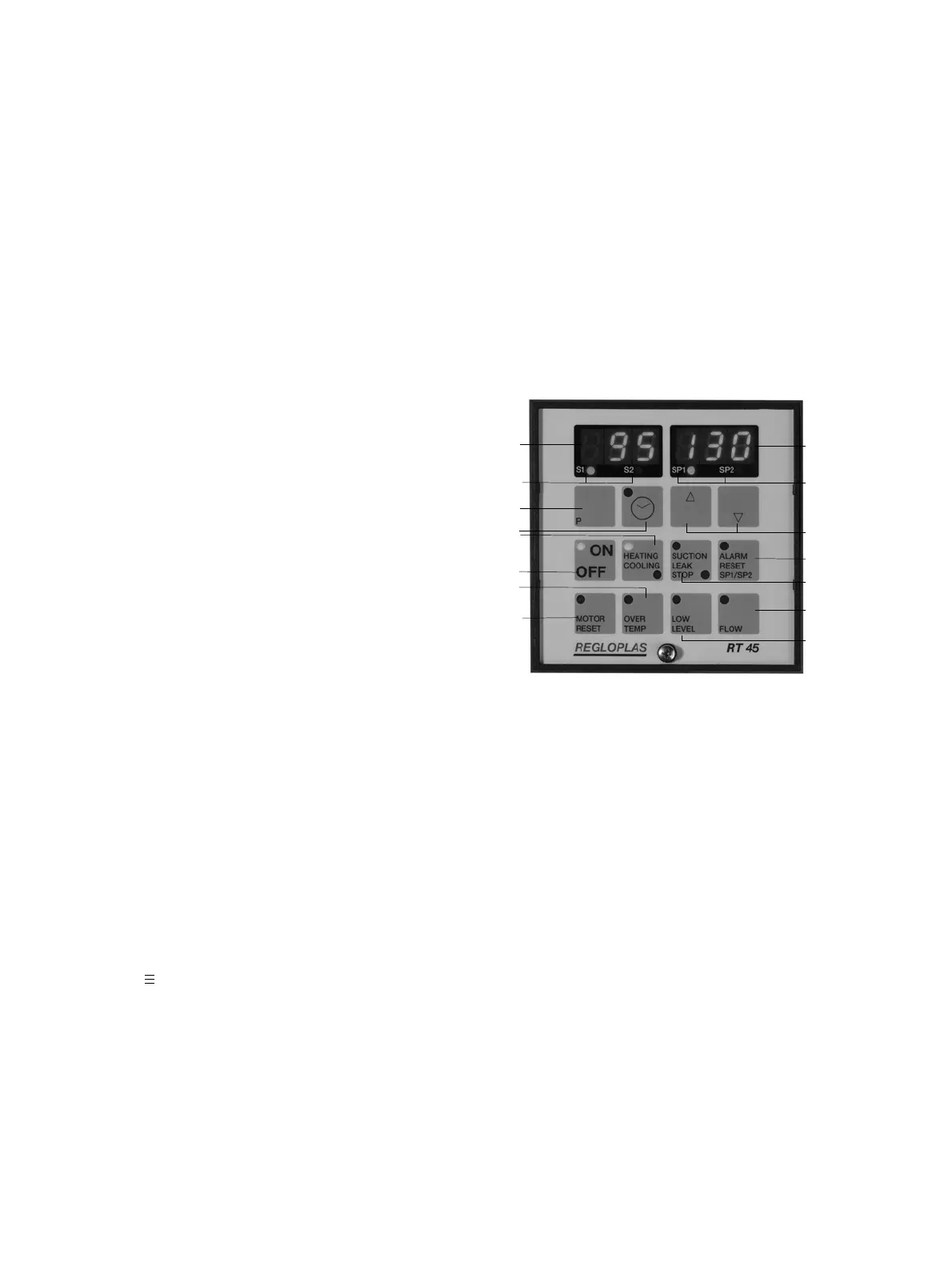
12 On/Off key with lamp indicating operation.
13 Lamps for heating and cooling.
14 Key for programming.
15 Key with lamp for programming the timer.
1
3
14
15
13
12
11
10
2
4
5
6
7
8
9
Fig. 1: Operating elements and displays
1. General Comments
The Regloplas RT 45 microprocessor control system consists of a control component with operating
and display elements, as well as a performance component built into the temperature control unit with
several inserts for accessories.
2. Range of Application
The RT 45 control system was developed for use in temperature control units (hereafter referred to as
“unit”). It enables dialog between one or more units and the processor of the production facility via an
interface as well as operation independent of the processor.
3. Control and indicating elements
(fig. 1)
1 Display for actual value at temperature sensor
Sn1 or Sn2 and malfunctions.
2 Display for set values SP1, SP2 and malfunc-
tions.
3 Lamps for the actual value of the outlet tem-
perature S1 (sensor Sn1) and the consumer tem-
perature S2 (sensor Sn2).
4 Lamps for the first and second set values SP1 or
SP2.
5 Keys for adjusting set values and programming.
6 Reset key with malfunction lamp for alarm, as
well as switching set values SP1–SP2 and vice
versa.
7 Key with lamps for drainage and leak-stop modes.
8 Key for flow indicator and malfunction lamp for
flow.
9 Malfunction lamp for level of heat transfer fluid.
10 Malfunction lamp for pump motor.
11 Malfunction lamp for overheating.
Switching on and off of the control system with the “On/Off” key.
Set-value and actual-value display. When the unit is turned on via the “On/Off” key, the set tempe-
rature “SP1” or “SP2” appears in the display to the right (2), while the actual temperature “S1” of the
internal probe Sn1 (fluid temperature) or “S2” of the external probe Sn2 (consumer temperature) ap-
pears in the display to the left (1).
Display of inlet and outlet temperatures. By pressing the keys “up” (∆) and “down” (∇) simulta-
neously, the inlet temperature “S3” will appear in the display to the right (or: “no” = probe not pre-
sent; S 3 probe defective). The outlet temperature “S1” will appear in the display to the left (the lamp
“S1” lights up).
“Up” (∆) and “Down” (∇) key (5). Increases and decreases the set value and changes the pro-
grammed value.
“Timer” key (15). Used for programming the timer, when present.
“P” key (14). Programming key.
“Heating/Cooling” lamps (13). When the upper lamp is lit, the unit is heating; when the lower lamp
is lit, the unit is cooling.
“Suction/Leak Stop” key with lamps (7). By pressing the key once, the unit is switched to leak-stop
mode. The lamp below the key lights up. Leak-stop mode is only possible when:
 Loading...