79
6
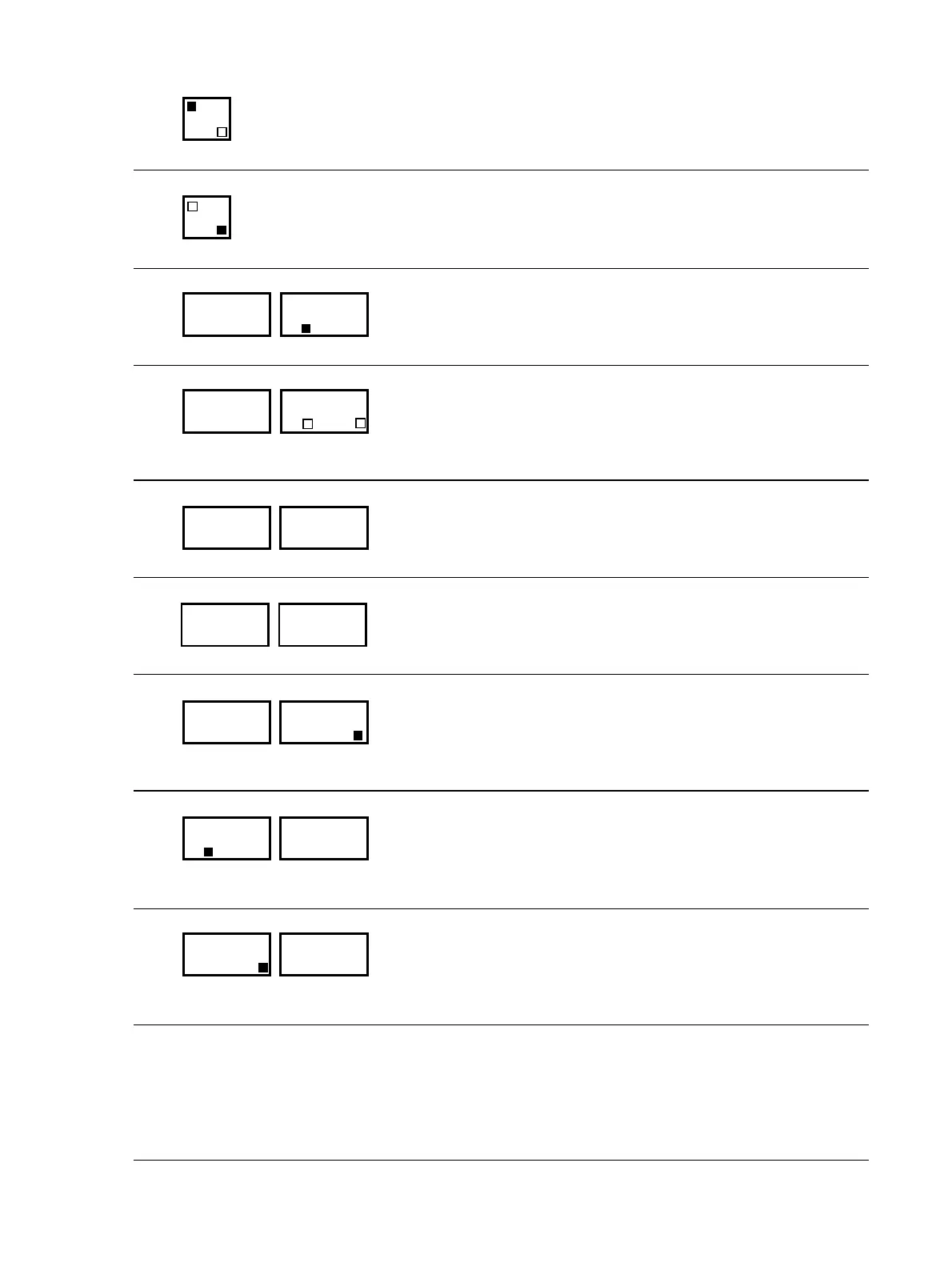
Suction mode (except P
140S) or drainage by compressed air is activated when the upper lamp is lit.
7
Leak-stop mode is activated when the lower lamp is lit (except P
140S).
8
In normal operation, the temperature set value SP1 is displayed.
9
Indicates the set value temperature when input externally (0 to 10 V or 0/4 to 20 mA). Neither “SP1”
nor “SP2” lights up.
10
In computer operation, the unit address is displayed, e.g. “A 2”.
11
Heating and cooling procedures are controlled externally.
12
Displays the second programmed set value SP2 and the “SP2” lamp. It is controlled in accordance
with SP2 (see Section 7.1, Programming “SP2”).
13
Displays the actual temperature of the internal sensor Sn1 (fluid temperature).
The “S1” lamp lights up.
14
Displays the actual temperature of the external sensor Sn2 (usually consumer temperature). The “S2”
lamp lights up.
6.2 Malfunction Displays
Procedure when a malfunction occurs (Alarm):
1 Switch off the alarm signal (e.g. horn) by pressing the “Alarm Reset” key. The “Alarm Reset” light
will go out.
2 Correct the malfunction.
3 Turn off the alarm display by pressing the “Alarm Reset” key again.
SUCTION
LEAK STOP
SUCTION
LEAK STOP
XXX 120
SP1
XXX 120
SP1 SP2
XXX A 2
. . .
XXX
XXX 120
SP2
XXX90
S1
XXX90
S2