At the heart of Reliable’s Single Interlock Preaction System is the
Model EX Valve. This valve is a hydraulically operated, straight-
through-design, differential-type valve (see Fig. 2). System
maintenance is simplified since priming water is not required and
the deluge valve can be reset externally without cover removal.
This is accomplished by pushing in and turning the external
reset knob at the rear of the valve (see Fig. 2). This feature
provides a significant system-restoration time advantage.
The Reliable Single Interlock Preaction System trim set (see Fig.
2) provides all of the necessary equipment for connections to the
valve’s pushrod chamber inlet and outlet ports, the main drain,
alarm devices, air supply, water supply, and required pressure
gauges. This valve is provided fully assembled with trim.
System Operation
To fully operate a Reliable Single Interlock Preaction System, two
independent events must coexist before water is discharged.
One electrical detector (two detectors in a cross-zoned system)
must activate and a sprinkler must open. Operation of the
detection system will cause the valve to open, but no water will
discharge since the sprinklers will not have opened. Opening of
a sprinkler in the absence of a detection signal will result in loss
of air or nitrogen pressure and activation of a low pressure alarm.
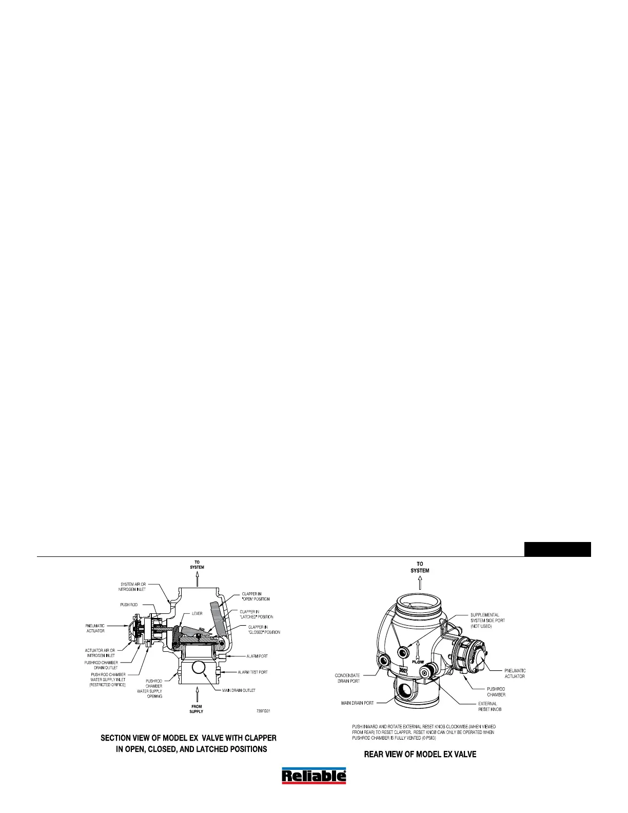
When set correctly for service, the Model EX Valve is
hydraulically established to withhold the supply water from the
sprinkler system piping. The Reliable Model EX Valve is shown in
both closed and open positions in Fig.2. In the closed position,
the supply pressure acts on the underside of the clapper and
also on the push rod through the push rod chamber’s inlet
restriction. The resultant force due to the supply pressure acting
on the push rod is multiplied by the mechanical advantage of
the lever and is more than sufficient to hold the clapper closed
against normal supply pressure surges.
When a fire is detected, the energized solenoid valves vent the
air from the pneumatic actuator, which in turn vents the push rod
chamber to atmosphere through the chamber’s outlet. Since
the pressure cannot be replenished through the inlet restriction
as rapidly as it is vented, the pushrod chamber pressure
falls instantaneously. When the pushrod chamber pressure
approaches approximately one-third of the supply pressure, the
upward force of the supply pressure acting beneath the clapper
overcomes the lever-applied force thereby opening the clapper.
Once the clapper has opened, the lever acts as a latch,
preventing the clapper from returning to the closed position.
Water from the supply flows through the EX Valve into the system
piping. Water also flows through the dry pipe alarm outlet to the
alarm devices.
After the system is shut down and drained, the Model EX valve
can be reset by pushing in and turning the reset knob at the
rear of the valve (see Fig.2). The external reset feature of the
Model EX Valve provides a means for simple, economical system
testing, which is one essential facet of a good maintenance
program.
The external reset feature does not, however, eliminate another
important facet of good maintenance, namely, periodic cleaning
and inspection of the internal valve parts. In the event that water
builds up inside the valve due to condensate from the air supply
system or water left inside from valve system testing, a drain is
available for venting. After closing the main supply valve, a small
valve over the drain cup can be opened slightly until the water
inside the valve body and the main pipe column has drained.
See the section titled “Draining Excess/Condensate Water From
System” in this bulletin for the detailed procedure.
The Model B Manual Emergency Station is also included in the
trim set. It consists of an aluminum nameplate mechanically
attached to a ball valve. The valve handle in its OFF position
is guarded against accidental turning to the ON position (and
system discharge) by a nylon cable tie provided with each trim
kit. The cable tie is inserted, after the system has been restored
for operation. The nylon cable tie is designed to allow, in case
of an emergency, forceful turning of the valve handle to the ON
position. As an alternative to the Model B Hydraulic Manual
Emergency Station, the Model A Hydraulic Manual Emergency
Pull Box (see Reliable Bulletin 506) is also available and can be
provided as an option.
Whenever ambient temperature conditions are high, the water
temperature in the Model EX Valve’s pushrod chamber could
possibly increase, thereby increasing the pressure in the
chamber to values exceeding the rated pressure of the system.
In an installation where standard temperatures are exceeded,
a pressure relief kit may be needed. Pressure relief kit, P/N
6503050001, can be installed into the pushrod chamber’s
releasing line to limit the pressure to 175 psi (12,1 bar).
Bulletin 739
June 2020
Page 3 of 9
www.reliablesprinkler.com
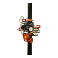
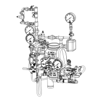
Model EX Type A Section and Rear Views
Figure 2
 Loading...