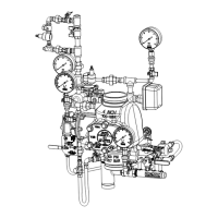
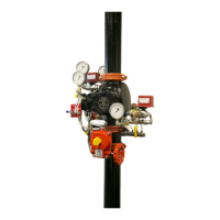
System Design Considerations
The automatic sprinklers, air compressor, releasing devices,
electric releasing control equipment, fire detection devices,
manual pull stations, and signaling devices which are utilized
with this Reliable Single Interlock Preaction System must be Loss
Prevention Certification Board (LPCB) approved, as applicable.
The system valve and all interconnecting piping must be located
in a readily visible and accessible location and in an area that
can be maintained at a minimum temperature of 40°F (4°C). Note:
Heat tracing is not permitted.
The redundant solenoid valves are operated and supervised by
an electrical releasing/control panel.
System Air Pressure Requirements
When a Reliable Single Interlock Preaction System is utilized,
the sprinkler system piping requires a minimum of 7 psi (0,5
bar) supervisory pneumatic pressure. The Model A Pressure
Maintenance Device, along with an additional air pressure
regulator, are used to maintain the system pneumatic pressure
between 7 and 10 psi (0,5 and 0,7 bar) where a dry nitrogen gas
supply or a clean, dependable, and continuous (24 hours per
day, 7 days per week) compressed air source is available.
The section of the preaction trim that contains the two redundant
normally-closed solenoid valves, and the supply to the pneumatic
actuator require pneumatic pressure settings per Table C. When
establishing the preaction system for service, refer to Table C
of this bulletin for the correct pneumatic pressure settings for a
corresponding water supply pressure.
Note: During the initial system set-up, a higher pneumatic
pressure may be required in order to properly seat the internal
diaphragm of the pneumatic actuator.
Refer to Reliable Bulletin 251 for instructions on how to modify
these pressure settings.
Bulletin 739
June 2020
Page 4 of 9
www.reliablesprinkler.com
Water Pressure
psi (bar)
Pneumatic Pressure to be Pumped
into Sprinkler System, psi (bar)
Maximum Not Less Than Not More Than
20 (1.4) 10 (0.7) 14 (0.9)
50 (3.4) 12 (0.8) 16 (1.1)
75 (5.2) 13 (0.9) 17 (1.2)
100 (6.9) 15 (1.0) 19 (1.3)
125 (8.6) 16 (1.1) 20 (1.4)
150 (10.3) 17 (1.2) 21 (1.4)
175 (12.1) 18 (1.2) 22 (1.5)
System Pressure
Table C
System Electrical Requirements
All releasing, alarm and detection devices in this Reliable Single
Interlock Preaction System are supervised by the Preaction
Panel Series 1000 MK4. The power supply, the standby
emergency power supply, battery charger, and the rectifier
circuitry are all contained within this panel. For additional and
detailed wiring information, refer to the manufacturer’s literature
included with the Releasing Control Panel.
Note: In order for the solenoid valve to maintain Reliable
warranty it must remain sealed as it came from the factory. If
there are concerns about the valve’s internal components,
immediate replacement is recommended.
Valve Size:
Equivalent Length:
Cv
C = 120 C = 100
2" (50mm) 4.4 ft (1,3 m) 3.1 ft (1,0 m) 101
2-1/2" (65mm) 6.0 ft (1,8 m) 4.3 ft (1,3 m) 236
76mm 7.7 ft (2,3 m) 5.5 ft (1,7 m) 241
3" (80mm) 12.6 ft (3,8 m) 9.0 ft (2,7 m) 254
4" (100mm) 14 ft (4,3 m) 10 ft (3,0 m) 469
165mm 29.4 ft (9,0 m) 20.9 ft (6,4 m) 886
6" (150mm) 29.4 ft (9,0 m) 20.9 ft (6,4 m) 886
8" (200mm) 53.5 ft (16,3 m) 38.1 ft (11,6 m) 1516
Friction Loss
Table D
 Loading...