Listing & Approvals
The LPCB approval for Single Interlock Preaction systems
states the system must comply with the general requirements
of the “LPC Rules for Automatic Sprinkler Systems (incorporat-
ing EN12845)” and in particular Technical Bulletin 208 “Sup-
plementary requirements for sprinkler installations which can
operate in the dry mode”.
Loss Prevention Certification Board (LPCB)
Installation Requirements of Preaction Systems Include:
1. The equipment must be installed, configured and
maintained in accordance with the manufacturers
specifications, by appropriately trained personnel.
2. The system shall be electrically monitored and be capable
of indicating “ready to operate” at all times.
3. Detectors should be LPCB approved and must be
compatible with the Control Panel.
4. Connecting cables shall comply with BS6387 (classification
C, W, Z).
5. Two LPCB approved Solenoid Valves shall be installed in
parallel, shall function in the pneumatic condition only and
be protected by a strainer.
6. Clean dry air (or Nitrogen) shall be used. An air
maintenance device shall be used, such that the inflow of
air cannot exceed the egress of air through one sprinkler,
or any other means of operating the valve.
9.
Clapper Gasket and Seat Replacement Procedure (cont.)
8 (cont). Reach into the valve and grasp the seat and remove
it from the valve. Then remove the clapper-mounting
ring subassembly from the valve. Visually examine all
components of the seat-clapper-mounting ring subassembly
replacing any component that appears damaged. New
O-rings should always be used for reassembly.
9. Reassembly: clean the bore of the valve body. Lubricate the
bore with O-ring grease. Lubricate and install the O-rings
onto the seat. Lubricate and install the mounting ring
O-ring into the body (8” (200mm) valve size only). Insert
the clapper-mounting ring subassembly into the handhold
opening of the EX Valve using caution to not damage or
dislodge the mounting ring O-ring (8” (200mm) valve size
only). Align the mounting ring so that the Lever is near
the pushrod and the mounting ring “ears” are between
the tabs of the valve body. Insert the seat into the valve
body and through the clapper-mounting ring subassembly.
Start to tread the seat into the body by hand, then tighten
the seat with the seat wrench until it bottoms out on the
mounting ring. Verify that the seat-clapper-mounting ring
subassembly is in the fully down position between the tabs
of the body, and check to see that the lever lines up with
the pushrod. Reassemble the handhold cover and set up
the Model EX Valve as per the section “Resetting Model EX
Valve Single Interlock Preaction Systems”.
Pushrod Chamber Diaphragm and O-Ring Replacement
Procedure
A small bleed hole is located on the underside of the pushrod
chamber. If there is air or water leakage coming out of the bleed
hole:
a. Disable detection system and supervisory pneumatic
supply to system.
b. Shut down the valve controlling water supply to the system.
Relieve the inlet pressure by opening the main drain valve.
Close the valve that supplies water to the pushrod chamber,
and open the Model B Manual Emergency Station.
c. Remove the trim at the unions nearest to the pushrod
chamber cover.
d. Take the pushrod chamber cover off by removing the six
retaining screws.
CONDITION ONE (Water coming out of the bleed
hole):
Water coming out of the bleed hole is caused by a leaking
diaphragm. Visually inspect the pushrod chamber cover and
piston to determine what could have damaged the diaphragm
and then correct. Install a new diaphragm. NOTE: The
diaphragm has two different surfaces; it is not bi-directional.
It will fail if installed backwards! Roll the diaphragm so that
the smooth surface (the pressure side) conforms to the inside
of the pushrod chamber cover and the fabric side engages
the pushrod, and reassemble the six retaining screws with an
installation torque of 15 foot-pounds in a star pattern. Set up the
Model EX Valve as per the section “Resetting Model EX Valve
Single Interlock Preaction Systems”.
CONDITION TWO (System Air coming out of the
bleed hole):
System air coming out of the bleed hole is caused by a
worn O-ring assembled to the pushrod guide. Remove the
piston-pushrod subassembly, pushrod spring, and pushrod
guide. installation torque for the pushrod guide is 35 inch-
pounds. CAUTION: Do not over tighten the pushrod guide.
Reassemble the components that were initially removed.
Re-install the diaphragm if it appears to be in good shape,
otherwise, replace it also. NOTE: The diaphragm has two
different surfaces; it is not bi-directional. It will fail if installed
backwards! Roll the diaphragm so that the smooth surface
(the pressure side) conforms to the inside of the pushrod
chamber cover and the fabric side engages the pushrod, and
reassemble the six retaining screws with an installation torque
of 15 foot-pounds in a star pattern. Set up the Model EX Valve
as per the section “Resetting Model EX Valve Single Interlock
Preaction Systems”.
Ordering Information
Specify:
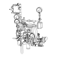
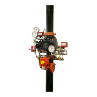
Model EX Single Interlock Preaction System Type A
• Size
• 2” (50mm)
• 2-1/2” (65mm)
• 3” (80mm)
• 76mm
• 4” (100mm)
• 6” (150mm)
• 165mm
• 8” (200mm)
• End Configuration
• See Table A
Bulletin 739
June 2020
Page 9 of 9
www.reliablesprinkler.com
 Loading...