Maintenance
The owner is responsible for maintaining the fire protection system
in proper operating condition. Any system maintenance or testing
that involves placing a control valve or detection/control system
out of service may eliminate the fire protection that is provided by
the fire protection system.
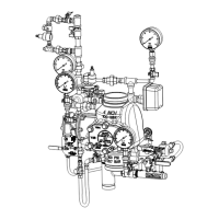
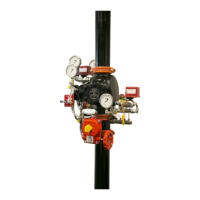
The Reliable Model EX valve and associated equipment shall
periodically be given a thorough inspection and test. NFPA
25, “Inspection, Testing, and Maintenance of Water Based
Fire Protection Systems,” provides minimum maintenance
requirements. System components shall be tested, operated,
cleaned, and inspected at least annually, and parts replaced
as required. Replace any components found to be corroded,
damaged, worn, or non-operable. Increase the frequency of
inspections when the valve is exposed to corrosive conditions
or chemicals that could impact materials or operation of the
assembly.
If face plate is removed during maintenance, torque face plate
bolts to the following values during re-installation:
• 35 ft-lbs. (47 N-m) for 2” through 4” valves
• 70 ft-lbs. (95 N-m) for 6”-8” valves
Draining Excess/Condensate Water from the System
1. Notify the owner and monitoring company that maintenance
is being performed on the system.
2. Close the main water control valve.
3. Open the Main Drain Valve.
4. Open the Condensate Drain Valve until all water has drained.
5. Close Condensate Drain Valve.
6. Partially open the Main Water Control Valve.
7. Slowly close the Main Drain Valve.
8. Fully open the Main Water Control Valve.
9. Notify the owner and monitoring company that the system
has been returned to service.
Clapper Gasket and Seat Replacement Procedure
1. Disable detection system and supervisory pneumatic
supply to system.
2. Shut down the valve controlling the water supply to
the system and open the main drain valve. Open the
condensate drain valve. Close the pushrod chamber supply
valve and open the Model B Manual Emergency Station.
3. Remove the EX Valve front (handhold) cover and inspect
the seat, clapper, and seal assembly for damage. If
inspection indicates damage to the seal assembly only,
replace as follows:
4. Remove the bumpstop nuts and remove the seal assembly
. Install a new seal assembly and thread the bumpstop
nuts onto the threaded studs of the seal assembly. Tighten
finger tight plus ¼ to ½ turn.
5. If inspection indicates damage to the clapper, proceed to
step 6.
6. At the rear of the valve, disconnect the condensate drain
trim section starting with the elbow connector. Then remove
the ¼” globe valve, followed by the ¾”x¼” reducing
bushing. Remove the retaining rings from the clapper hinge
pin, push the hinge through the condensate drain opening
and remove the clapper subassembly. Install a new clapper
subassembly in the reverse order making sure the clapper
spacers are in their proper position.
7. If the seat is damage, or it is suspected that the leakage is
through the seat O-rings, proceed to step 8.
8. Using Reliable P/N 6881603000 Seat Wrench for 2”
(50mm), 2½” (65mm), 76mm and 3” (80mm) valve sizes,
Reliable P/N 6881604000 for 4” (100mm) valve size,
Reliable P/N 6881606000 for the 6” (150mm) and 165mm
valve sizes or Reliable P/N 6881608000 Seat Wrench for 8”
(200mm) valve size, remove the seat by unscrewing. This
will loosen the seat-clapper-mounting ring subassembly.
8.
Bulletin 739
June 2020
Page 8 of 9
www.reliablesprinkler.com
Solenoid Valve
WARNING: The owner is responsible for maintaining the
fire protection system in proper operating condition. Any
system maintenance or testing that involves placing a control
valve or detection system out of service may eliminate the
fire protection of that system. Prior to proceeding, notify
all authorities having jurisdiction. Consideration should be
given to employment of a fire patrol in the affected area.
WARNING: Prior to operating the solenoid valve,
be sure to close the system control valve to avoid
unintentional operation of the system.
1. Inspections: It is imperative that the system be inspected
and tested in accordance with NFPA 25 on a regular
basis. The frequency of the inspections may vary due to
contaminated water supplies, corrosive water supplies,
or corrosive atmospheres. In addition, the alarm devices,
detection systems, or other connected trim may require a
more frequent schedule. Refer to the system description
and applicable codes for minimum requirements.
2. The valve must be inspected at least monthly for cracks,
corrosion, leakage, etc., cleaned and replaced as necessary.
3. If leakage is suspected through the solenoid
valve, it should be replaced.
Troubleshooting
1. Mechanical sprinkler alarm not operating: This is most
likely caused by a clogged screen in the strainer of the
water motor. Proceed as follows: Remove plug from the
strainer. Remove and clean the screen. Replace the screen
and the plug, and then tighten securely (Ref. Bulletin 613).
2. Water leaking from Ball Drip. This can be
caused by either a water column on top of
the clapper or a supply water leakage.
a. Leakage due to water column. This condition is
caused by leakage past the clapper seal assembly. Be
sure the clapper seal and seat are free of any type of
debris or damage. If necessary, follow steps below to
replace the seal assembly and/or seat.
b. Supply water leakage. This condition is caused by
leakage past the lower seat O-ring. Follow steps below
for inspection and/or replacement of lower seat O-ring.
3. Air or nitrogen leaking from Ball Drip. This
condition is caused by leakage past either the
clapper seal assembly or the upper seat O-ring.
a. Clapper seal leak. Be sure the clapper seal and
seat are free of any type of debris or damage. If
necessary, follow steps below to replace the seal
assembly and/or seat.
b. Upper seat O-ring. Follow steps below for
inspection and/or replacement of upper seat
O-ring.
 Loading...