IN-2000
7
2. INSTALLATION
2.1. Unpacking
2.1.1. Chair
2.1.1.1. Open the shipping carton carefully and record any
shipping damage to the carton or to the contents.
2.1.1.2. Remove all contents from the shipping carton
and note that models with a Backrest are packed with the
Backrest removed.
2.1.1.3. To level the chair, tilt chair on its side and screw
all four hex shaped levelers in all the way. Position the chair
in its proper location. Note if any of the levelers do not
touch the oor. Tilt chair and screw out appropriate leveler
approximately half the distance required for it to reach the
oor. Now adjust the leveler diagonal from the rst one
adjusted until all four levelers are in contact with the oor.
2.1.1.4. Plug the Power Cord into a grounded 120 volt,
60 Hertz electrical outlet capable of supplying at least 2.7
amperes. (120V Model)
2.2. Assembly
2.2.1. Backrest
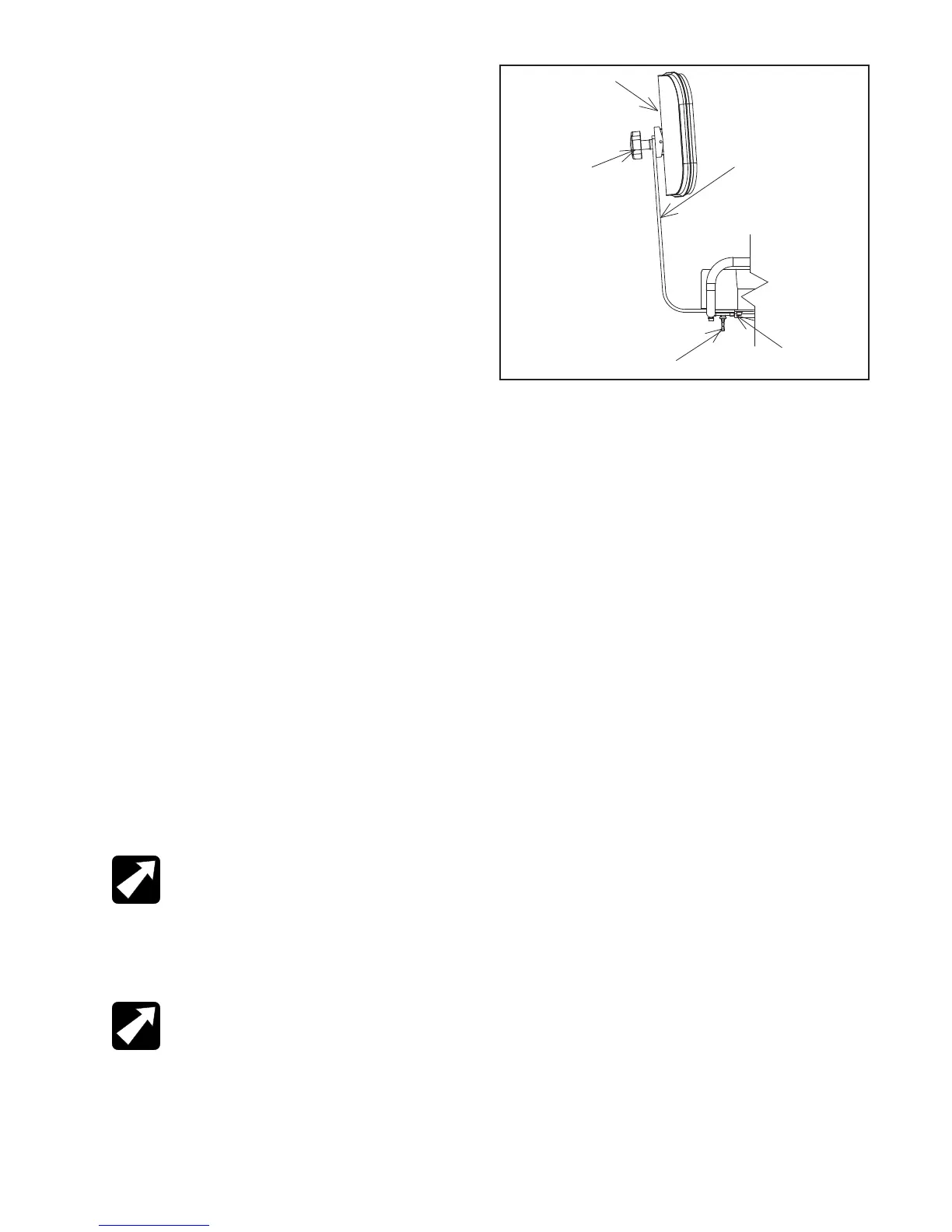
2.2.1.1. To assemble, loosen the Thumbscrew (ltem 3,
Figure 1) and remove the Back Support (ltem 4, Figure 1).
Re-install the back support in its correct (upright) position
and tighten the Thumbscrew.
2.2.1.2. Remove the upholstered Back Assembly (ltem 1,
Figure 1) from the smaller box and remove the Handwheel
(ltem 2, Figure 1) and two Washers (Item 11, & Item 12,
Figure 5). lnsert the stud on the upholstered back through
the slot in the Back Support and the Washers on the same
side as the Handwheel.
2.2.1.2.1. Hold the upholstered back in the correct position
and tighten the Handwheel.
FIGURE 1
4
5
3
2
2.2.2. Power Receptacle
2.2.2.1. Locate the Footswitch Assembly and the Power
Cord Assembly. Refer to Figure 4 for receptacle location
and attach all cables.
3. OPERATION
3.1. Rotation
3.1.1. The Chair Top may be rotated a full 360°. The lock
which prevents rotation is controlled by a Hand Lever with
a black handle located below the seat and on the patient’s
right side.
3.1.2. Push the Lever down to release the Lock and lift to
engage the Lock.
3.2 Seat Back Adjustment
3.2.1. The Backrest can be adjusted vertically and
horziontally (Figure 1).
3.2.2. To adjust the Backrest vertically loosen the black
knob (Item 2). Move the Backrest to the desired position
and tighten the knob.
3.2.3. To adjust the Backrest horizontally loosen the thumb
screw (Item 3). Move the Back Support Bar (Item 4) to the
desired position and tighten the Thumb Screw securely.
NOTE: After Support Bar has been inserted
into Back Support per the assembly
instructions (Section 2.2), insert Stop Screw
into threaded hole in end of Support Bar. The
#10-24 x ¼ Round Head Machine Screw
(Part Number 2037299) is shipped in the
parts bag.
REMARQUE: Après que la barre de soutien
ait été insérée dans l’appui arrière par
instructions d’assemblée (section 2.2),
insérez la vis d’arrêt dans le trou fileté dans
l’extrémité de la barre de soutien. Les #10-
24 la vis principale que ronde de machine de
¼ de X (numéro de la pièce 2037299) est
embarquée dans les pièces mettent en sac.