Page 11
4. Wipe clean and refit level plug. Tighten to a torque of 2.07
to 2.76 kg/m (15 to 20 lb/ft)
Check and top up level of rear axle oil
1. Place the vehicle on ramp or over pit.
2. Wipe clean the level plug and surrounding area and remove
plug (figure 11).
3. Observe oil level which is correct when level with the
bottom of the level hole threads.
4. If necessary, top up via the level hole, using a pump type oil
can with a flexible nozzle, charged with a recommended oil, until the
level is correct.
5. Wipe clean the level plug and refit. Tighten to 2.07 to 2.76
kg/m (15 to 20 lb/ft)
Lubricate drive shaft
1. Place the vehicle on ramp or over pit.
2. Using a grease gun charged with a recommended lubricant.
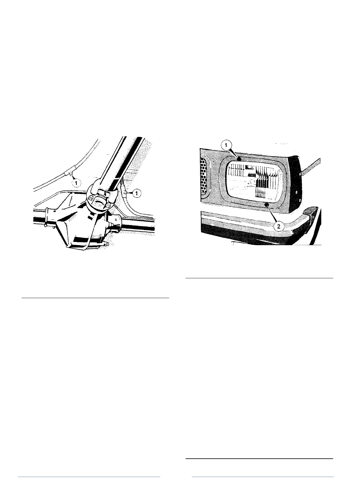
Figure 13 Handbrake cable grease nipples
1. Grease nipples
Apply grease via the nipple located at the gearbox end of the drive
shaft and to the nipple on each of the universal joints.
Lubricate handbrake cable and cable guides
1. Place the vehicle on ramp or over pit.
2. Using a grease gun charged with a recommended lubricant,
apply grease to the cable by means of the two grease nipples (figure
13) Apply grease at any area of the exposed inner cable and liberally
coat the cable guides on the axle with grease to prevent the inner
cable binding on the guides.
Check hydraulic system and fuel system pipes for chafing, leaks
and corrosion
Follow the run of all brake hydraulic pipes and ensure that at no point
are they chafing against body or frame members. Note and report any
corroded section of pipe. Examine all joints for leaks whilst a second
person applies pressure to the brake pedal. Check that the flexible
hoses are not kinked or strained when the steering is turned from lock
to lock.
Examine the run of the fuel line from tank to carburettor and ensure
that at no point is it chafing against the body or fouling components.
Check the rubber connections between sections of pipe are not
unduly stained, perished or split.
Check exhaust system for leakage and security
Check security of the exhaust connections and manifold bolt
tightness. Examine the system for corrosion and deterioration.
Check tightness of suspension fixings, tie-rod levers, steering unit
attachments and steering universal coupling bolts plus check
gaiters for damage
Rear suspension
1. Check tightness of nuts and bolts securing the leaf springs
and shackles to the frame.
2. Check tightness of nuts and bolts securing the upper and
lower ends of the dampers to the rear axle and chassis frame.
Figure 14 Headlamp adjusting screws
1. Horizontal adjustment screw.
2. Vertical adjustment screw.
Front suspension
3. Check tightness of all nuts and bolts securing the upper and
lower wishbones to the frame.
4. Check upper and lower fixings of the coil spring damper
units.
5. Check nuts connecting the lower wishbones to the vertical
link fulcrum.
6. Check security of the track rod ends to steering arm nuts.
7. Check tightness of all anti roll bar fixings.
Steering unit attachment
8. Check tightness of rack assembly fixings - 2.07 to 2.5 kg/m
(15 to 18 lb/ft).
9. Check for and ascertain cause for any backlash in the
steering.
10. Examine steering rack gaiters and check condition / leakage.
Steering rack couplings
11. Check pinch bolts through universal couplings - 3.46 to 4.15
kg/m (25 to 30 lb/ft).
Check tightness of drive shaft connecting bolts
1. Place the vehicle on ramp or over pit.
2. Check tightness of coupling bolts at both ends of propellor
shaft - 3.46 to 4.15 kg/m (25 to 30 lb/ft).
 Loading...
