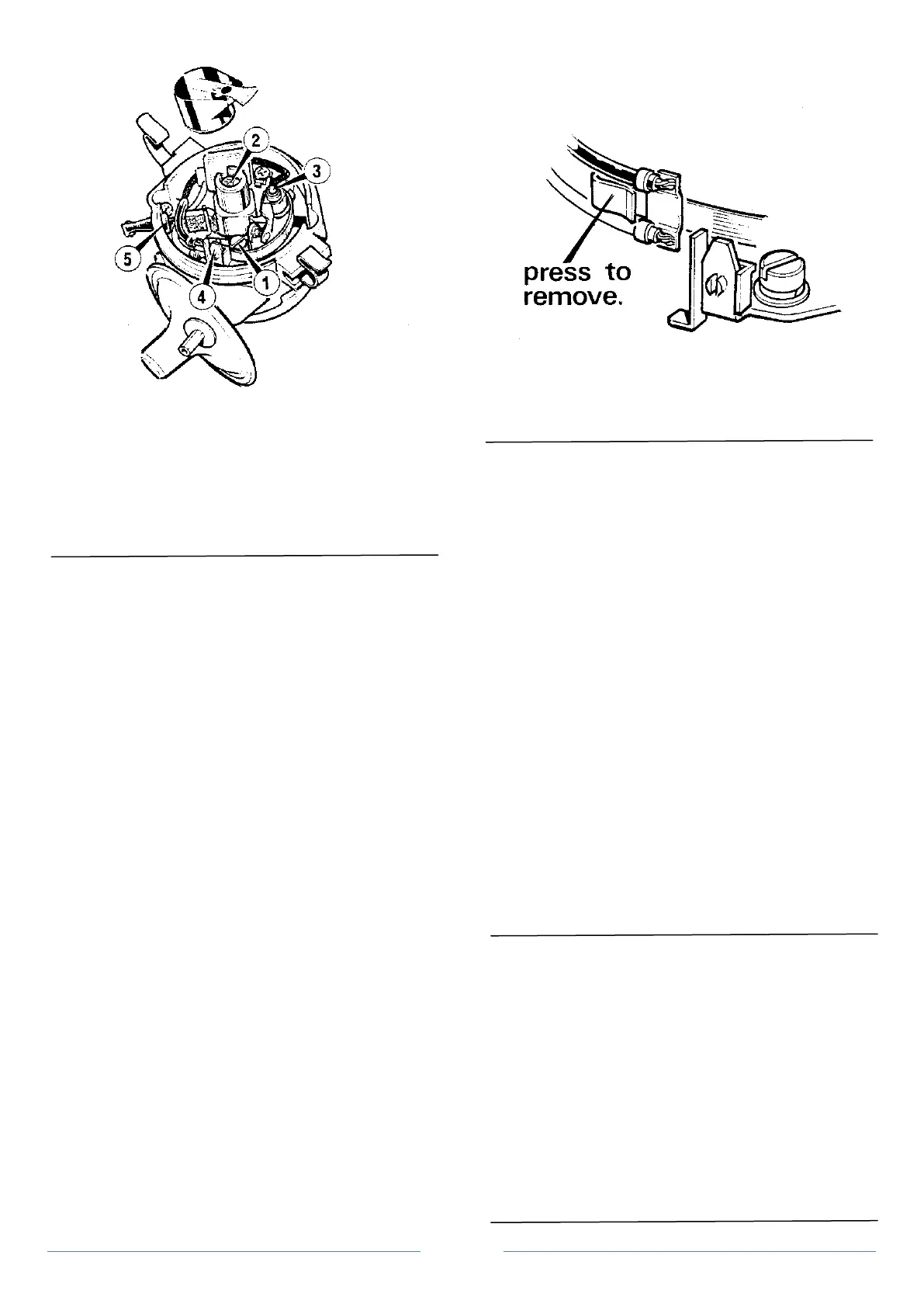
Figure 3 Contact breaker adjustment
1. Locking/adjustment screw
2. Cam spindle lubrication pad
3. Breaker arm pivot point
4. Terminal post
5. Low tension lead
Operation 1 Removal & examination of contact breaker
points
1. Remove the distributor cap and rotor arm.
2. Press the terminal end of the moving contact spring
towards the cam (Figure 4). this will disengage the spring from the
insulating piece attached to the terminal post. The capacitor lead and
the low tension fly-lead can then be detached from the folded end of
the spring. remove the slotted screw securing the fixed contact and
lift the assembly from the base plate.
3. Check the condition of the points for signs of wear or
burning on the contacts. If this is apparent, the complete assembly
will need replacing. Contacts showing a greyish colour and only
slightly pitted can be smoothed with a fine emery stone and then
thoroughly cleaned with carbon tetrachloride.
To replace
1. When refitting or replacing a contact breaker set, it is
important to note that the capacitor and low tension fly-lead
connecting terminal in the folded end of the moving contact spring
has the cable clips facing outward. Otherwise the lower clip may foul
the fixed contact plate short circuiting the contact breaker. (Figure 4)
2. Replace the slotted screw and adjust the contact breaker
points as previously described.
Note: If a new contact set is fitted, set the contact gap to 0.40 to 0.45
mm (0.016 to 0.019 in) to allow for initial bedding in of the plastic
heel.
3. Replace the rotor arm and distributor cap.
Operation 2 Condenser - removal & replacement
The condenser is fitted in parallel with the contact breaker points. A
short circuit in the condenser will cause ignition failure as the contact
points will no longer interrupt the low tension circuit. In such cases
the condenser will need replacing.
An open circuit, however, cannot be readily checked without the use
of specialised equipment such as a diagnostic test set. The usual
symptoms of this are excessive arcing and burning of the contact
Figure 4 Correct replacement of points
breaker points and difficult starting.
To remove the condenser
1. Remove the distributor cap and rotor arm.
2. Remove the contact breaker assembly
3. Remove the cross head screw and lift the condenser from
the base plate.
4. The condenser, condenser lead and low tension fly-lead are
a complete assembly. The fly-lead, complete with grommet and
insulated "lucar" terminal should be withdrawn through the hole in
the distributor body (Figure 2).
5. replace in reverse order taking care that there is no
possibility of a short circuit between the condenser lead terminal and
the contact breaker plate.
Note: Dismantling of the complete distributor is not recommended as
only the cap, rotor arm, condenser and lead assembly and contact
breaker assembly are available as spares.
Operation 3 To remove the distributor from the engine
1. Disconnect the spark plug leads and "King" lead to the coil.
2. Remove the low tension fly-lead from the coil.
3. Unscrew the single colt and washer securing the distributor
clamp to the block, and withdraw the distributor. Do not disturb the
clamping bolt securing the clamp to the distributor body.
4. Replace in reverse order.
Distributor specification
Type Lucas 45D4 single pair
contact breaker points
Drive Dog-gear from camshaft
Firing order 1, 3, 4, 2.
Ignition advance Vacuum
Static timing 10°BTDC
Rotation Anti-clockwise (from above)
Firing angle 0-90°- 180°- 270°+/- 1°
Dwell angle 51° +/- 5°
Contact breaker gap 0.38 mm (0.015 in)
0.40-0.45 mm (0.016-0.018
in) for new contact set
Contact spring loading 522-880 gf (18-24 ozf)
Condenser 0.18 to 0.25 microfarads
 Loading...
