Connection of the
medium piping
■
The connection of the lines
on-site takes place on the front
side of the unit.
■
For the purpose of servicing,
connections must be equipped
with shut-off valves and flow
volumes adjusted using pipe leg
regulating valves.
■
Additional automatic bleed
valves are to be provided in the
supply and return at the instal-
lation's highest point.
■
The medium piping may not
exert any structural load on the
unit.
■
The line connections may not
generate any thermal or me-
chanical stresses on the unit.
If necessary cool line or support
with the second tool.
■
If the unit is at first to be oper-
ated with only a part of the
entire system, the medium flow
for the missing system compo-
nents is to be simulated using
a pipe leg regulating valve.
■
The pipe sizing is to be de-
signed so that the required
minimum flow volume is not
under-cut.
A permanent large flow volume
must be ensured to realise the
minimum flow volume.
!
CAUTION
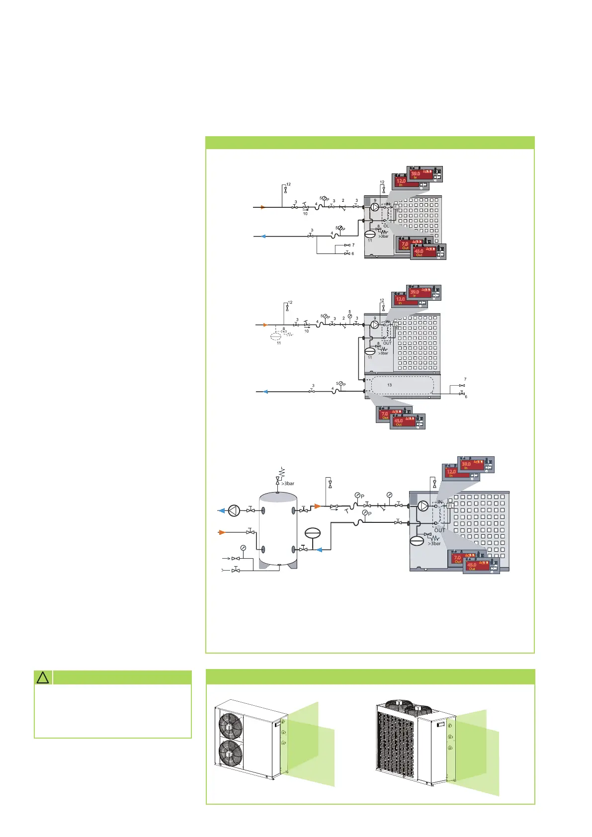
KWL 130(H) - 370(H) with external medium storage tank (accessory)
KWL 130 (H) - 370 (H) with external medium storage tank (hydr. switch)
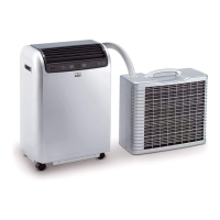
Pipe routeing
KWL 130(H) - 220(H)
free pipe
routeing
possible
free pipe
routeing
possible
No pipe routeing possible
no pipe
routeing possible
KWL 270(H) - 370(H)
Necessary system components
Diagram of the System components
Legend:
1 Differential pressure switch
2 Dirt trap
3 Shut-off valve
4 Compensator
5 Pressure gauge
6 Draining
7 Manual bleeder
8 Safety valve
9 Circulation pump
10 Valve for hydronic balancing
11 Diaphragm expansion vessel
12 Bleeding valve
13 Medium storage tank (accessory)
KWL 130(H) - 370(H)
REMKO KWL (H)
22