Renesas RA Family AIK-RA6M3, v1 User's Manual
R12UZ0143EE0100 Rev.0.1 Page
of 25
Oct.15.23
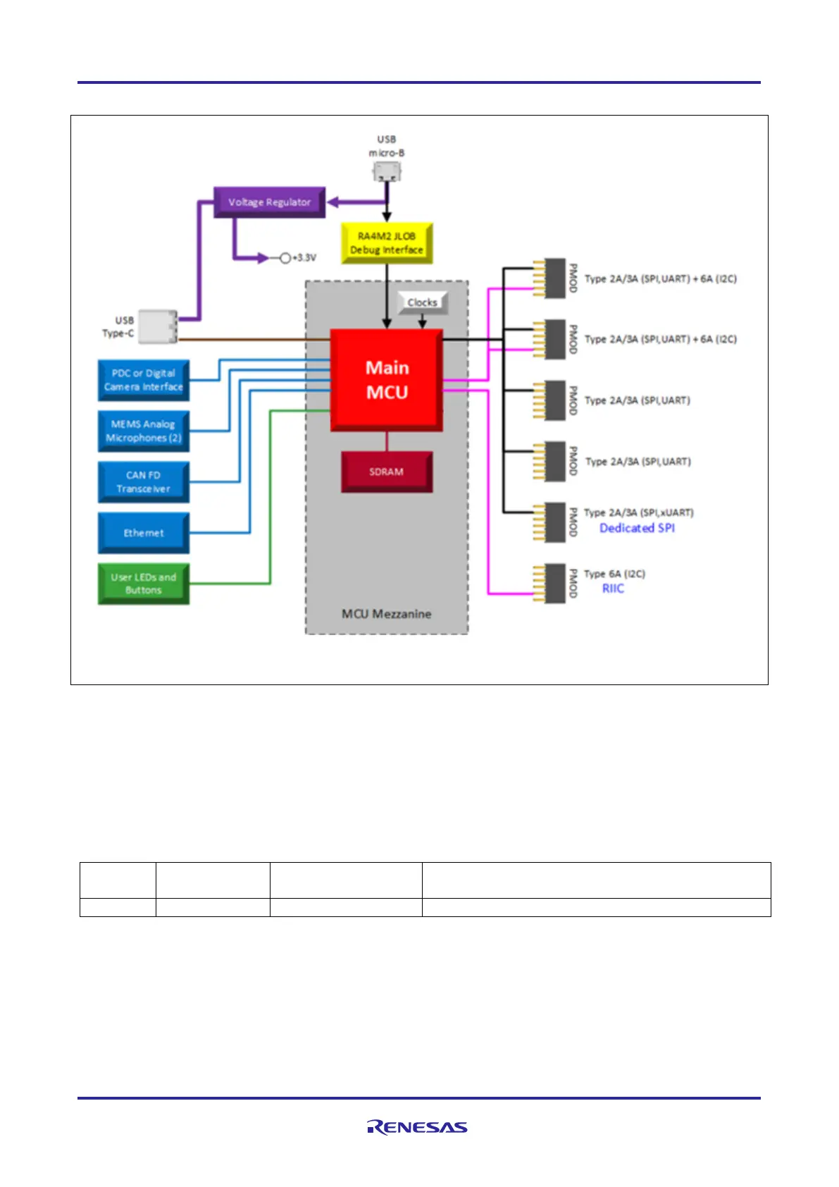
5.1.1 System Block Diagram
Figure 5. AIK-RA6M3 Block Diagram
5.2 General Features
5.2.1 Jumper Settings
5.2.1.1 Default Board Configuration
The following table describes the default settings for each jumper on the AIK-RA6M3.
The Circuit Group for each jumper is the designation found in the board schematic.
Table 1. Default Jumper Settings
Configures the MCU for normal boot mode
5.2.2 Power Requirements
AIK-RA6M3 is designed for +5V operation. An on-board Low Dropout Regulator (LDO) is used to convert the
5V supply to 3.3V, which is then used to power the main MCU and many of the peripheral features of the
AIK-RA6M3.
5.2.2.1 Power Supply Options
AIK-RA6M3 can be powered in three different ways as described in this section.

 Loading...


