RL78/G13 Safety Function (Frequency Detection)
Symbol: TMR05
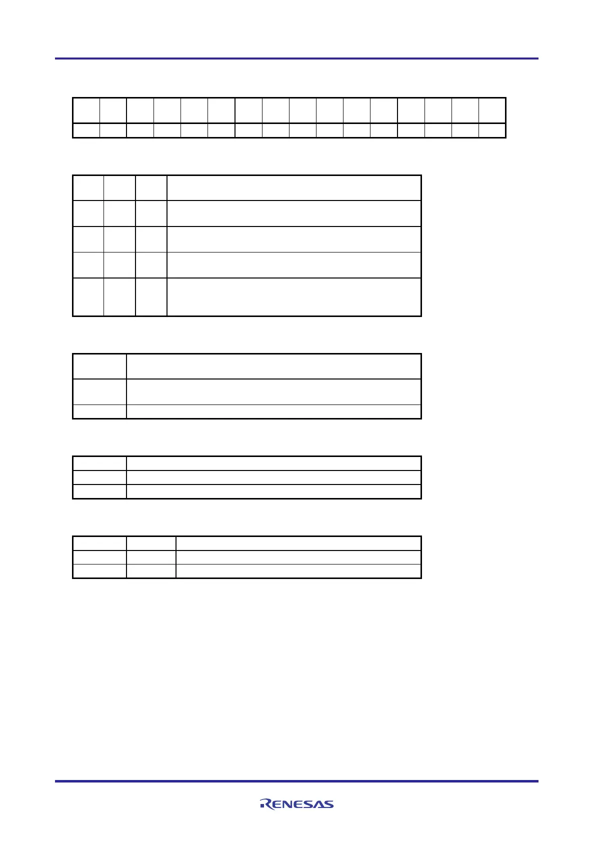
15 14 13 12 11 10 9 8 7 6 5 4 3 2 1 0
R01AN0956EJ0100 Rev. 1.00 Page 34 of 70
Feb. 27, 2012
CKS CKS 0 CCS 0 STS STS STS CIS CIS 0 0
MD MD MD MD
051 050 05 052 051 050 051 050 053 052 051 050
1 0 0 0 0 0 1 0 0 0 1 0 0 0 0 0
Bits 10 to 8
STS STS STS
002 001 000
Setting of start trigger or capture trigger of channel 0
0 0 0
Only software trigger start is valid (other trigger sources are
unselected).
0 0 1
Valid edge of the TI00 pin input is used as both the start
trigger and capture trigger.
0 1 0
Both the edges of the TI00 pin input are used as a start trigger
and a capture trigger.
1 0 0
Interrupt signal of the master channel is used (when the
channel is used as a slave channel with the simultaneous
channel operation function).
Bit 11
MASTER00
Selection between using channel n independently or simultaneously with
another channel(as a slave or master)
Operates in independent channel operation function or as slave
channel 0 simultaneous channel operation function.
0
Operates as master channel in simultaneous channel operation function. 1
Bit 12
Selection of count clock (f
TCLK
) of channel 0
CCS00
0 Operation clock f
MCK
specified by the CKS000 and CKS001 bits
Valid edge of a signal input to the TI00 pin 1
Bits 15 and 14
Selection of operation clock (f
MCK
) of channel 0
CKS001 CKS000
Operation clock CK00 set by the PRS register 0 0
1 0 Operation clock CK01 set by the PRS register
Caution: For details on the register setup procedures, refer to RL78/G13 User's Manual: Hardware.

 Loading...


