RL78/G13 Safety Function (Frequency Detection)
Setting up the channel 5 operation mode
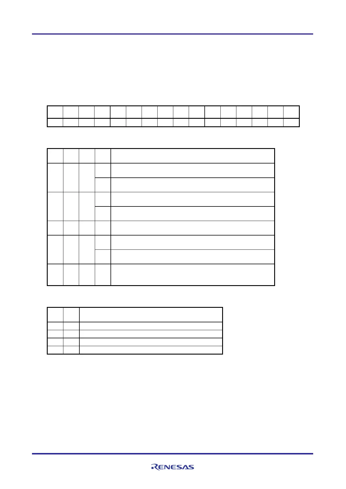
Timer mode register 05 (TMR05)
: Specify the operation mode and start the software trigger.
Select the ope
ration clock.
Sym
bol: TMR05
15 14 13 12 11 10 9 8 7 6 5 4 3 2 1 0
CKS
R01AN0956EJ0100 Rev. 1.00 Page 33 of 70
Feb. 27, 2012
051
CKS
050
0 CCS 0 STS
05 052
STS
051
STS
050
CIS
051
CIS 0 0
MD
050 053
MD
052
MD
051
MD
050
1 0 0 0 0 0 1 0 0 0 1 0 0 0 0 0
Bits 3 to 0
MD MD MD MD
Operation mode of channel 0
053 052 051 050
0
Interval timer mode.
(Timer interrupt is not generated when counting is started)
0 0 0
1
Interval timer mode.
(Timer interrupt is generated when counting is started)
0
Capture mode
(Timer interrupt is not generated when counting is started)
0 1 0
1
Capture mode
(Timer interrupt is generated when counting is started)
0 1 1 0
Event counter mode
(Timer interrupt is not generated when counting is started)
0
One-count mode
Start trigger is invalid during counting operation.
1 0 0
1
One-count mode
Start trigger is valid during counting operation.
Capture & one-count mode
1 1 0 0
T
imer interrupt is not generated when counting is started.
Start trigger is invalid during counting operation.
Bits 7 and 6
CIS CIS
Selection of TI00 pin input valid edge
001 000
0 0 Falling edge
0 1 Rising edge
1 0 Both edges (when low-level width is measured)
1 1 Both edges (when high-level width is measured)
Caution: For details on the register setup procedures, refer to RL78/G13 User's Manual: Hardware.
 Loading...


