For more information please refer to the hardware setup notes (RZ_N1S_DB_Board_Setup_Notes) and
schematics (RZ_N1S_DB_Board_Schematic) in respective board documentation folder in Solution Kit.
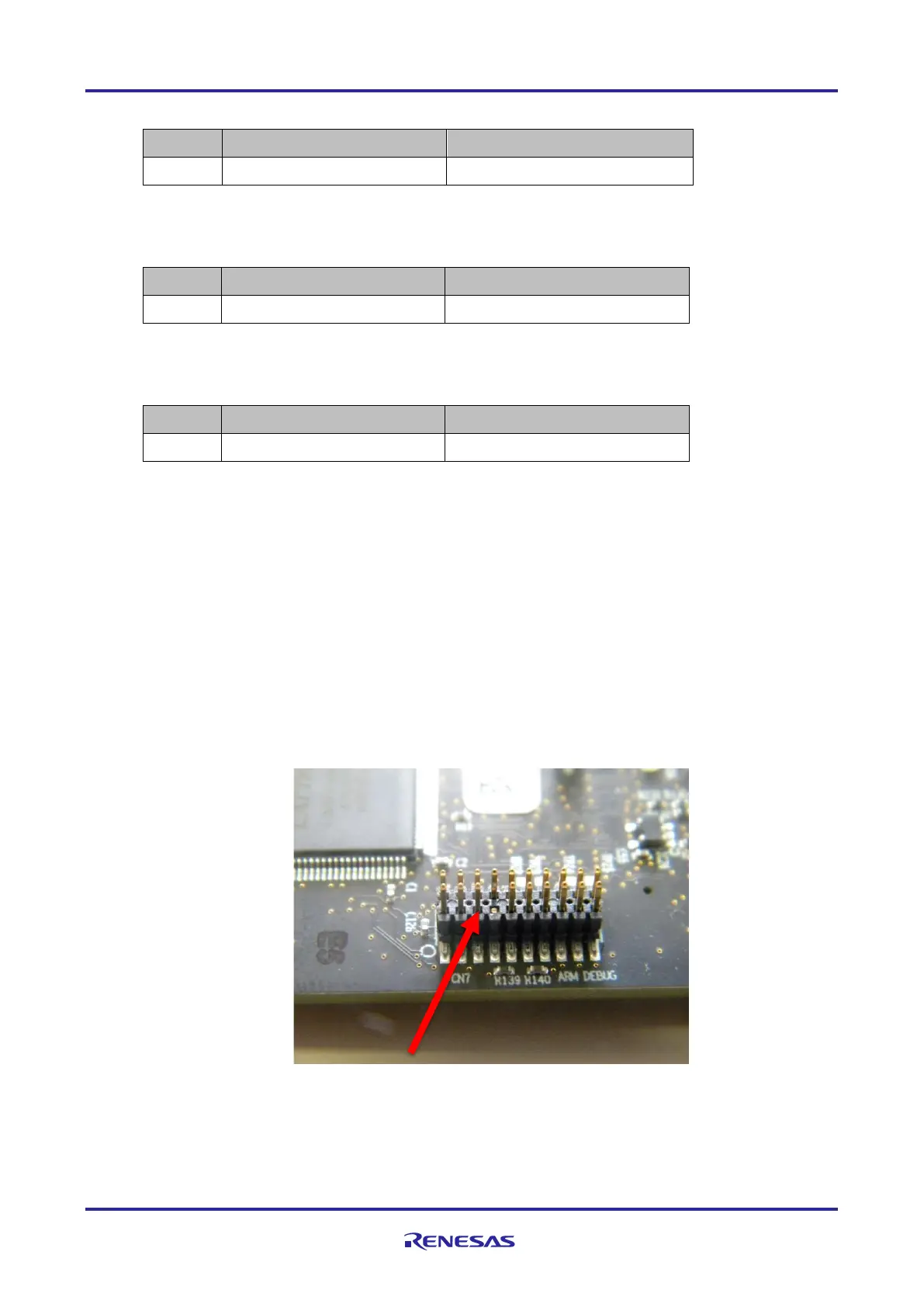
1. JTAG Debug Connector
This connection is required for software development purposes, to be able to run and debug the
software on the target. The IAR Debugger cable has one unused key pin, therefore pin 7 of the CN7
connector should be cut or bent, as shown below. After this step, you can attach your I-jet debugger
to the board via JTAG cable.
Figure 2-2: Connector CN10 with removed pin 7

 Loading...


