EasyManua.ls Logo

Renishaw RGH20 User Manual

Renishaw RGH20
19 pages
To Next Page IconTo Next Page
Page #1 background imageLoading...
Page #1 background image
RGH20 RESR angle encoder system
Installation guide
M-9561-0005-06-A
Question and Answer IconNeed help?

Do you have a question about the Renishaw RGH20 and is the answer not in the manual?

Renishaw RGH20 Specifications

General IconGeneral
BrandRenishaw
ModelRGH20
CategoryMedia Converter
LanguageEnglish

Summary

Compliance and General Information

Regulatory Compliance

FCC and RoHS compliance statements.

Additional Information

Further information, disclaimer, and disposal guidance.

Storage and Handling Guidelines

Component Handling

Guidelines for handling ring, readhead, and system components.

Cleaning and Environmental

Approved cleaning agents and environmental specifications.

RGH20 RESR Installation Drawings

'A' Section Ring Dimensions

Dimensions and tolerances for the RESR 'A' section ring.

Limit Switch Installation Details

Details on installing the limit switch.

'A' Section RESR Detailed Drawings

Dimensions and Tolerances Table

Detailed dimensions and tolerances for the 'A' section RESR.

Mounting Hole & Section Views

Specifications for mounting holes and section A-A.

'B' Section RESR Detailed Drawings

Dimensions and Tolerances Table

Detailed dimensions and tolerances for the 'B' section RESR.

Mounting Hole & Section Views

Specifications for mounting holes and section A-A.

Mounting Options and Procedures

Taper Mount: Initial Steps

First two steps for taper mount installation.

Taper Mount: Shaft & Component Specs

Shaft, roundness, finish, and diameter specifications for taper mount.

Taper Mount Installation: Advanced Steps

Steps 3-6: Screw Adjustment & Torquing

Steps 3 through 6 for taper mount installation.

Interference Fit Mounting Method

Alternative mounting method using interference fit.

Interference Fit Shaft Specs

Shaft specifications for interference fit mounting.

Reference Marks and Quick Start Guides

Reference Mark Options & Installation

Various reference mark options and their installation.

Quick Start: RGH20 Direct Output

Quick guide for RGH20 direct output installation.

Quick Start: RGH20F/REF System

Installation and calibration for RGH20F/REF.

Readhead Alignment and Reference Mark Setup

Readhead Mounting & Alignment

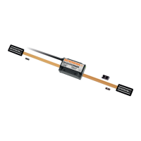
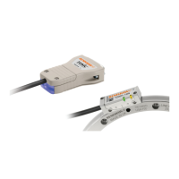
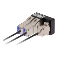
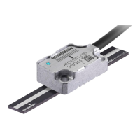
Procedures for mounting and aligning the readhead.

Reference Mark Setup & Phasing

Setting up and phasing the reference mark.

Limit Switch Functionality

Describes the function of the limit switch.

RGH20 Direct Output Readheads: Specifications

General Specifications

Power, environmental, mass, and cable details.

Output Signal Types & Pinouts

Overview of digital and analogue output signals and pin assignments.

RGH20 Direct Output Readheads: Connections & Speed

Electrical Connections: Grounding & Shielding

Grounding and shielding for RGH20 readheads.

Maximum Speed & Clock Frequency

Max speed and clock frequency for digital readheads.

Signal Termination Recommendations

Signal termination for digital and analogue outputs.

RGH20 Direct Output Readheads: Output Details

Digital Output Signal Characteristics

Detailed specifications for digital output signals.

Analogue Output Signal Characteristics

Detailed specifications for analogue output signals.

Alarm Functionality Description

Description of the 3-state alarm feature.

RGH20F/REF System: Interface Features

REF Interface Capabilities

Overview of REF interface features.

Self-Tuning Correction Mechanisms

Active correction for system accuracy.

System Calibration and Setup

Procedures for system calibration and incremental signal calibration.

Calibration Management & AGC Control

Manual exit, factory defaults, and AGC switching.

LED Indicator Status Guide

Guide to LED indications, status, and alarm output.

RGH20F/REF System: General & Output Specs

General System Specifications

Power, environmental, mass, and cable details.

Output Signal Pin Assignments

Pin assignments for analogue and digital outputs.

Analogue & Digital Output Details

Specific details for analogue and digital outputs.

RGH20F/REF System: Installation & Connections

REF Interface Installation Diagram

Diagram of the REF interface installation.

Electrical Connections & Shielding

Grounding and shielding for the RGH20F/REF system.

Cable Lengths & Signal Termination

Maximum cable lengths and signal termination.

RGH20F/REF Systems: Speed Performance

Digital System Speed Performance

Table of digital system speeds vs. resolution and clock frequency.

Analogue Output Performance Graph

Graph showing signal amplitude vs. frequency for analogue output.

RGH20F/REF Systems: Output Characteristics

Digital Output Signal Characteristics

Specifications for REF digital output signals.

Analogue Output Signal Characteristics

Specifications for REF0000 analogue output signals.

Set-up Signal Voltage Graph

Graph showing set-up signal voltage vs. amplitude.

Related product manuals