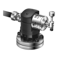
12 Recommended connection diagram for TS27R with HSI-C interface
Probe
status
Normally
open
(NO)
Normally
closed
(NC)
Probe
triggered
Closed Open
Probe
seated
Open Closed
HSI-C interface
SSR probe type and external
LED connector (5-way)
29. Probe type NO
28. Probe type common
27. Probe type NC
26. External LED 10 Vdc
25. External LED 0 Vdc
SSR probe status connector
(5-way)
24. Probe status NO
23. Probe status common
22. Probe status NC
21. Not connected
20. Not connected
Inhibit connector (5-way)*
10. Inhibit input
11. Inhibit return
12. 0 Vdc
13. +12 Vdc to +30 Vdc out
(fused at 100 mA)
14. Not connected
Power connector (4-way)
1. +12 Vdc to 30 Vdc supply input
2. 0 Vdc supply
3. 0 Vdc supply
4. Screen
Probe connector (5-way)
19.
18.
17. Screen
16. Standard probe input +
15. Standard probe input −
CNC controller
+12 Vdc to 30 Vdc
0 Vdc
Machine ground
(“star point”)
Connect either
pin24 or pin22,
but do not connect
both pins
Connect either
pin29 or pin27,
but do not connect
both pins
Block 4
Red
Blue
Block 1
Block 3
Block 5
Block 6
* Probe inhibit function. Refer to
the HSI-C hard-wired system
interface – congurable
installation guide (Renishaw
part no. H-6527-8501) for
connection information
NOTE: When
connecting the TS27R
probe to the HSI-C
interface, please use
the connection labelled
STANDARD PROBE.
Machine tool
Possible earth
path through base
screws of TS27R
Machine reference
ground
TS27R tool
setter
TS27R
probe
100 nF
capacitor

 Loading...