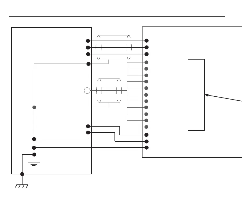
14 Recommended connection diagram for TS27R with MI 8-4 interface
CNC controller
+Vdc from I/O supply
SKIP input (G31)
Screen
Yellow/green
Yellow/green
Power to
interface
+Vdc
0 Vdc
Yellow/green
Controller
protective earth**
Optional
{
Yellow/green
Controller protective ground
** Can also be referred to as
‘PE starpoint’ or ‘earthplate’
MI 8-4 interface
B1 +Vdc
B2 0 Vdc
B3 screen
}
Power input
−Vdc from I/O supply
A10 isolated output + supply
A11 probe status output (totem pole)
A12 isolated output − supply
B4 SELX− input
B5 X− output
B6 SELX+ input
B7 X+ output
B8 SELZ− input
B9 Z− output
B10 SELZ+ input
B11 Z+ output
A7 inspection select
A8 inhibit
A9 input resistors common
 Loading...