15
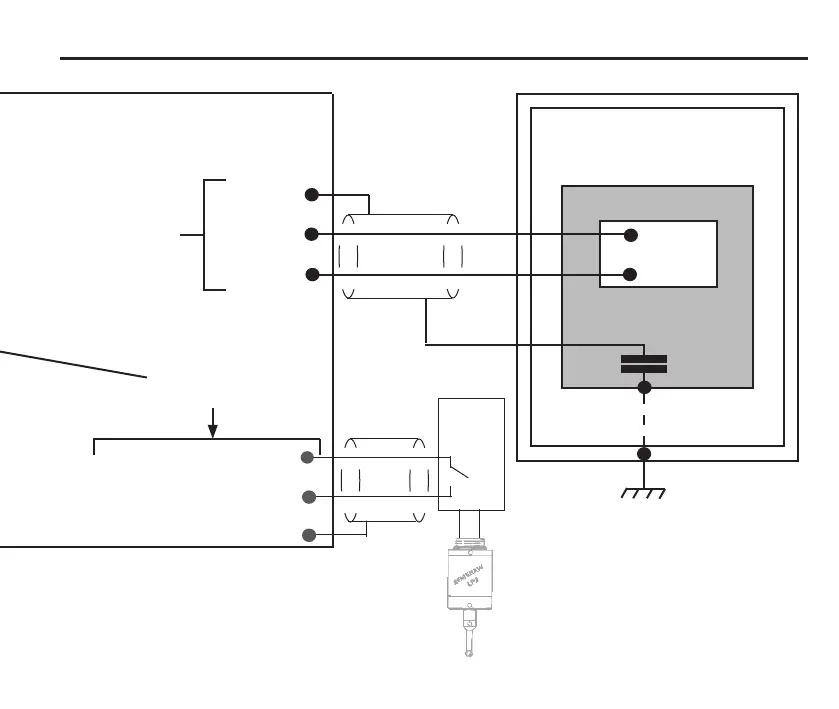
Recommended connection diagram for TS27R with MI 8-4 interface
For information regarding
these connections, see
the MI8-4 interface unit
installation and user’s
guide (Renishaw part no.
H-2000-5008).
Probe + A2
Probe − A3
Screen A1
Probe input
Blue
Red
Inspection system input + A4
Machine tool
TS27R tool setter
TS27R probe
Possible earth
path through base
screws of TS27R
100 nF
capacitor*
Machine reference ground
* The 100 nF capacitor prevents dc
and low frequency ac owing in
the cable’s screen due to differences
in potential between the controller’s
reference ground and the machine’s
reference ground.
Inspection system input − A5
Screen A6
Optional
Inspection
probe
interface
Inspection probe
 Loading...