14
NOTE: Damage to the Renogy inverters due to reverse polarity is NOT covered by
warranty.
NOTE: The input terminals of the inverters have large capacitors connected to
them. Once a positive and negative wire are connected to the terminals, it will
complete the circuit, and commence drawing a heavy current momentarily. As a
result, there may be a sparking occurring even if the inverter is in the off position.
To minimize sparking, it is recommended that the user have the appropriate size
wire feeding into the inverters and/or install an external fuse leading into the
inverter.
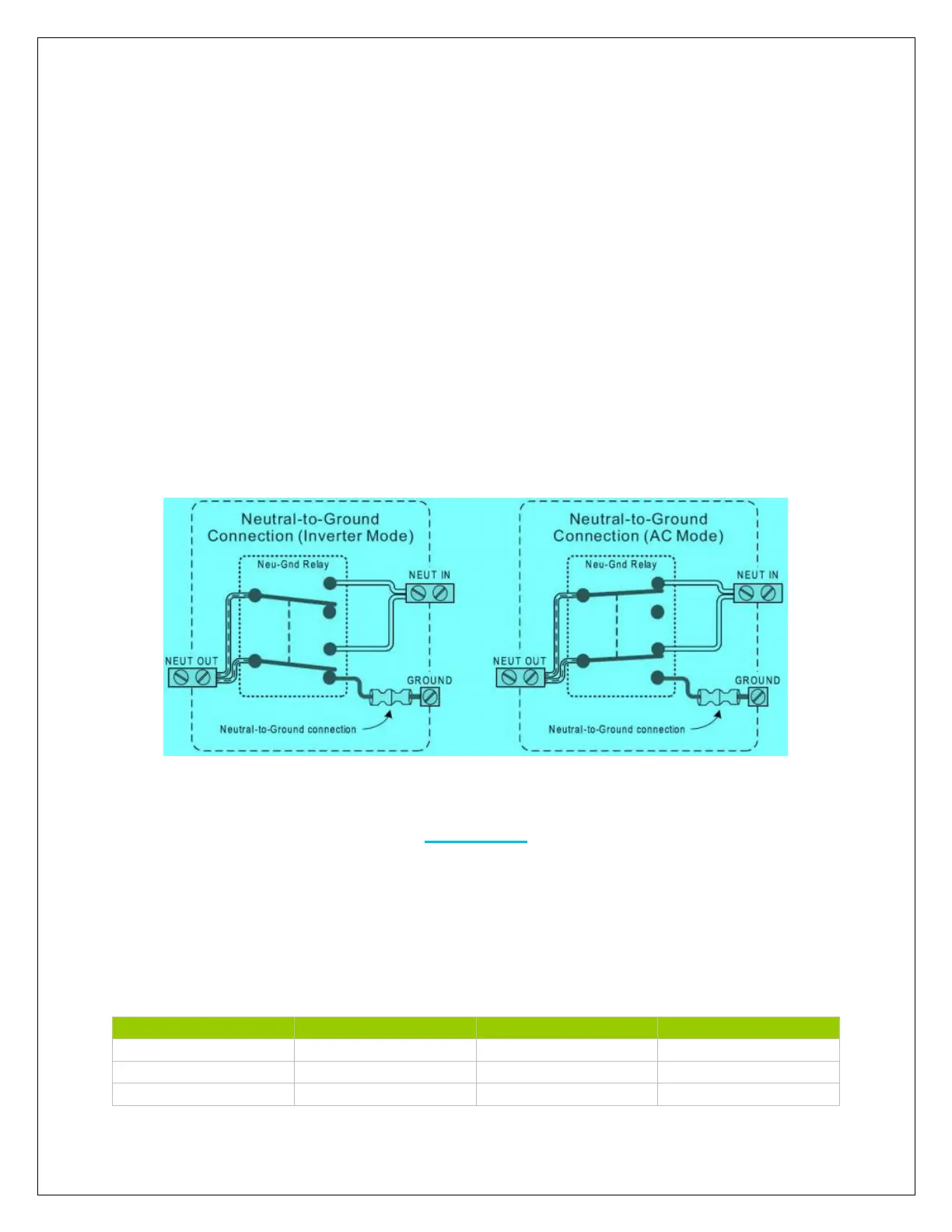
The Renogy Inverter Charger is equipped with an automatic neutral-to-ground switch.
The inverter uses an internal relay to connect the AC neutral output to the
vehicles/boats ground in inverter mode and disconnects it when an external AC source
is detected.
Operation
AC Charger
The Renogy inverter comes equipped with a 4-stage battery charger and an 8-battery
type selector switch. The charging current can be adjusted from 25%-100%. The
charging current will vary depending on the inverter model.
 Loading...