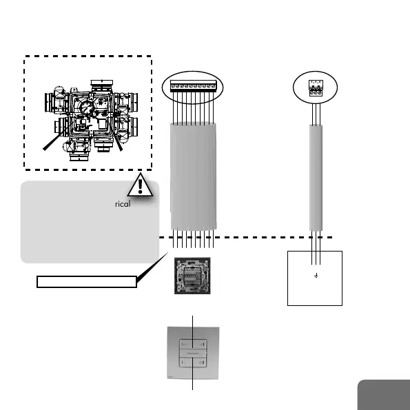
EN 19
L PE N
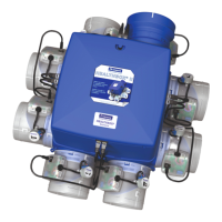
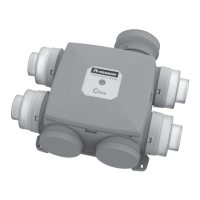
321DCBA C2C1 4
➊
➋
➊ ➋
Mains cable
3G1.5 mm
2
pre-wired tube
3G2.5 mm
2
3G1.5 mm
2
I
max
= 2,5 AAC
ex. LIYY, SVV
Connection cable XVK4
Min. 10x0.34 mm
2
Max. 10x0.8 mm
2
50Hz
230V AC ±10%
supply
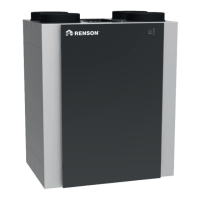
Installation area
Healthbox® II
Max. 30 m Max. 30 m
XVK4 - 4 position switch, potential free
Fusebox
Max. 2 switches
parallel
cover NIKO
®
type intense,
colour Sterling
I = input
0 = output
B 2
I 0
A 1
I 0
I 0
D 4
I 0
C 3
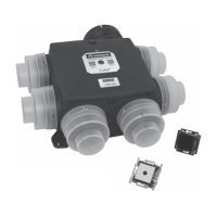
2 • Electrical wiring
2.1 • Healthbox
®
II (Compact)
ATTENTION:
the installation and electrical
connection of the various
components can only be
performed by qualified personnel
in accordance with general safety
measures and regulations.
C1 A B C D C2 1 2 3 4
 Loading...