List of tables
Table 1. KrosFlo® TFF System – Auxiliary Scale parts ......................................................................... 7
Table 2. Auxiliary scale keys ............................................................................................................. 10
Table 3. Auxiliary scale menu ........................................................................................................... 11
Table 4. Auxiliary scale menu navigation ......................................................................................... 11
Table 5. Good weighing practices .................................................................................................... 12
Table 6. Calibration report variable list ............................................................................................ 18
Table 7. GLP weighing printout variable list ..................................................................................... 19
Table 8. GLP date and time printout variable list ............................................................................. 20
Table 9. Scale Data ........................................................................................................................... 21
Table 10. Working mode settings ...................................................................................................... 22
Table 11. Save mode options ............................................................................................................. 22
Table 12. Weighing – Local settings ................................................................................................... 23
Table 13. Parts Counting – Local settings ........................................................................................... 23
Table 14. +/- control – Local settings ................................................................................................. 25
Table 15. Percent Weighing – Local settings ...................................................................................... 26
Table 16. Peak Hold – Local settings .................................................................................................. 27
Table 17. Totalizing – Local settings ................................................................................................... 27
Table 18. Animal Weighing – Local settings ....................................................................................... 28
Table 19. Troubleshooting suggestions .............................................................................................. 31
Table 20. Error messages ................................................................................................................... 31
List of figures
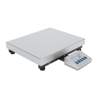
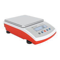
Figure 1. KrosFlo® TFF System - Auxiliary Scale components ............................................................. 7
Figure 2. Auxiliary scale parts ............................................................................................................. 7
Figure 3. Grounding spring check ....................................................................................................... 8
Figure 4. Rubber feet installation ....................................................................................................... 8
Figure 5. Weighing pan installation .................................................................................................... 9
Figure 6. Leveling the scale ................................................................................................................ 9
Figure 7. Interface cable to scale connection ..................................................................................... 9
Figure 8. Interface cable to octopus cable ....................................................................................... 10
Figure 9. Auxiliary scale keypad ....................................................................................................... 10
Figure 10. Calibration report example ............................................................................................... 19
Figure 11. GLP printout example ........................................................................................................ 19
Figure 12. Totalizing printout example .............................................................................................. 28
Figure 13. Scale dimensions ............................................................................................................... 30
Figure 14. Scale connectors................................................................................................................ 30
Figure 15. RS-232 connector .............................................................................................................. 30